
Rotor blade for a wind turbine

a technology for wind turbines and rotor blades, which is applied in the direction of wind motors, wind motors with parallel air flow, motors, etc., to achieve the effect of relatively cost-effective installation

Active Publication Date: 2017-01-26
WOBBEN PROPERTIES GMBH
View PDF12 Cites 3 Cited by
  • Summary
  • Abstract
  • Description
  • Claims
  • Application Information

AI Technical Summary

Benefits of technology

The patent describes a way to connect two blade parts, the rotor blade inner and outer parts, by using a thickened portion. This thickened portion is arranged parallel to the expected airflows when the rotor blade is in operation and helps create a stable connection with good aerodynamic properties. A barrier plate or barrier disc is also used to improve the connection. The technical effect is the creation of a reliable and efficient connection between the rotor blade inner and outer parts that improves the performance of the rotor blade.

Problems solved by technology

Alternatively, however, the rotor blade tip can also, for example, form a separate part, but this is not the case here.

Method used


Image

  • Rotor blade for a wind turbine
  • Rotor blade for a wind turbine
  • Rotor blade for a wind turbine

Examples


Embodiment Construction

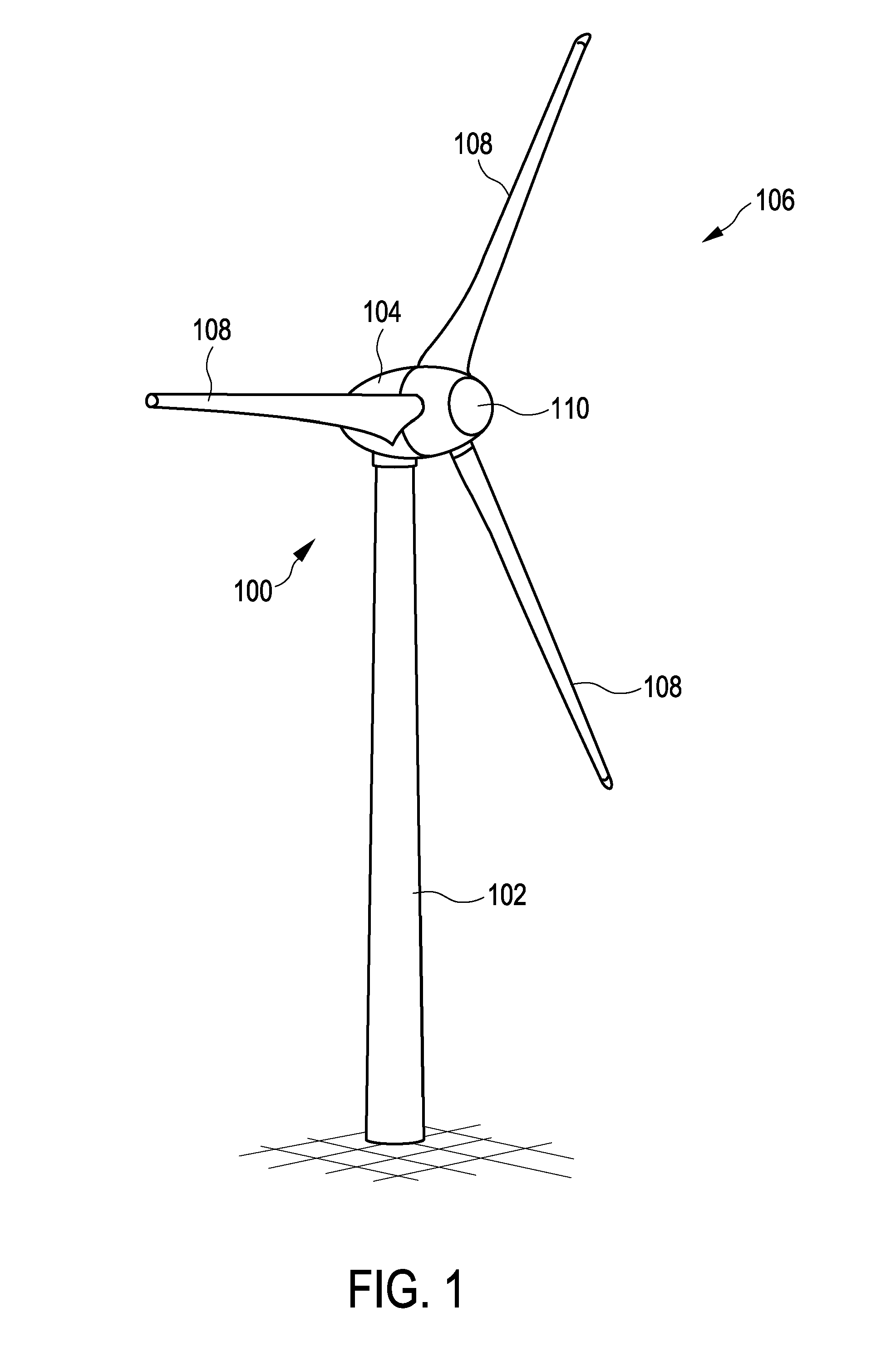
[0050]FIG. 1 shows a wind turbine 100 with a tower 102 and a nacelle 104. A rotor 106 with three rotor blades 108 and a spinner 110 is arranged on the nacelle 104. The rotor 106 is set in rotational motion by the wind and as a result drives a generator in the nacelle 104.

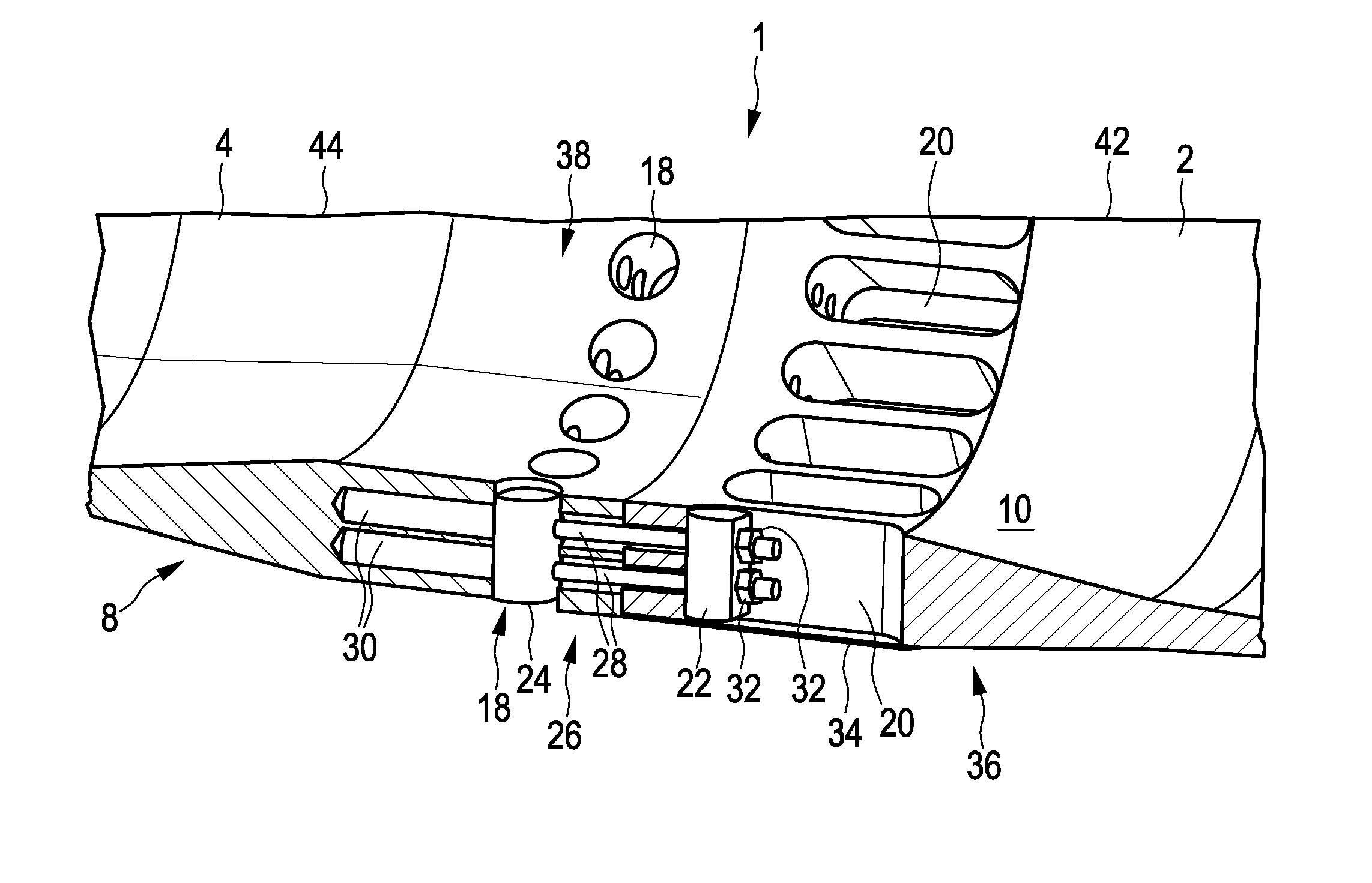
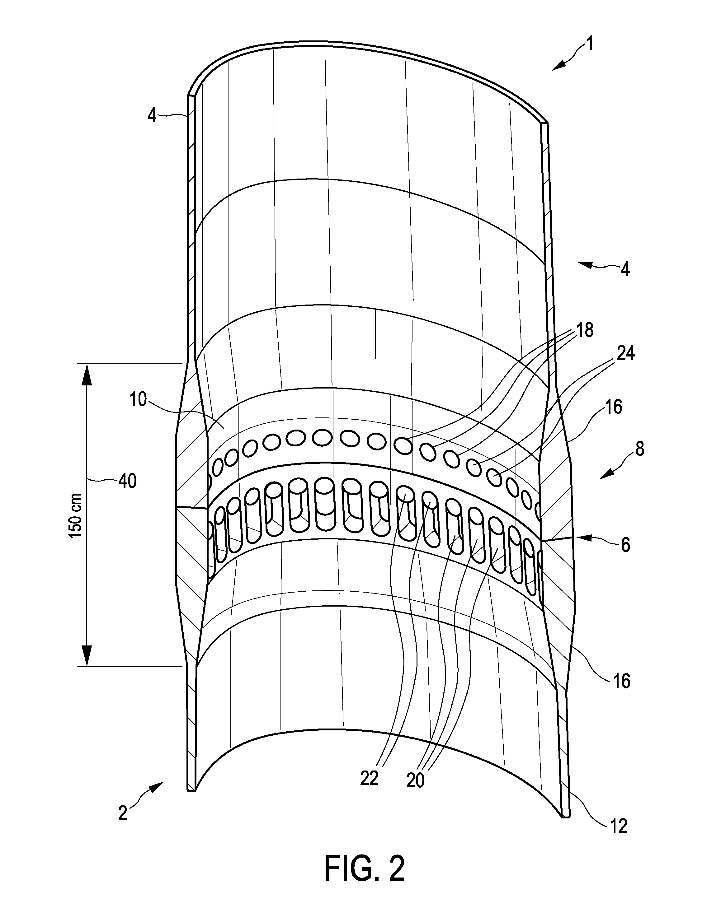
[0051]FIG. 2 shows a portion of a rotor blade 1 with a rotor blade inner part 2 and a rotor blade outer part 4. The drawing also shows the division of the section of the rotor blade 1 shown into multiple more or less rectangular areas, which serves for the computational splitting-up into regions with the same material coordinate systems but does not need to explained in more detail here.

[0052]Apart from that, the rotor blade inner part 2 and the rotor blade outer part 4, which can also be referred to more simply as the inner blade 2 and the outer blade 4 respectively, are connected to each other in the region of a joint 6. A separating disc or the like could also be arranged in this region as a boundary layer fence....


PUM


Abstract

A rotor blade for a wind turbine comprising a blade root to be fastened to a rotor hub, a blade tip opposite the blade root, a rotor blade longitudinal axis extending from the blade root to the blade tip, an inner rotor blade part on the near side of the blade hub, especially encompassing the blade root, and an outer blade part on the far side of the blade hub, especially encompassing the blade tip. The inner rotor blade part and the outer rotor blade part are joined to one another in a joining zone which forms a bulge in the rotor blade.

Description

BACKGROUND[0001]Technical Field[0002]The present disclosure relates to a wind turbine rotor blade and to a wind turbine having such a rotor blade. The present disclosure moreover relates to a method for producing a wind turbine rotor blade.[0003]Description of the Related Art[0004]Wind turbines are known and the currently most common type of wind turbine is a so-called horizontal-axis wind turbine, usually having three rotor blades. The dimensions of such wind turbines are getting bigger and bigger, namely in particular they have a higher hub or axis height and a larger rotor diameter with a correspondingly larger generator and greater feed-in power. Larger rotor diameters mean larger rotor blades which need to be transported from where they are manufactured to the respective site of erection. In particular the need to transport such long rotor blades, which can now have lengths as great as approximately 60 meters, regularly makes it necessary to use multi-part rotor blades.[0005]Su...

Claims


Application Information

Patent Timeline
Patent Type & Authority Applications(United States)
IPC IPC(8): F03D1/06
CPCF03D1/0675F05B2280/6003F05B2220/706F05B2260/301F05B2240/302Y02E10/72
Inventor HOFFMANN, ALEXANDER
Owner WOBBEN PROPERTIES GMBH
Learn More