
E-vaping device

a vaping device and electronic technology, applied in the direction of ohmic-resistance heating, ohmic-resistance heating details, immersion heating arrangements, etc., can solve the problem of discoloration of gauze and wick near the heating coil

Active Publication Date: 2016-12-15
AKRIA CLIENT SERVICES LLC
View PDF5 Cites 53 Cited by
  • Summary
  • Abstract
  • Description
  • Claims
  • Application Information

AI Technical Summary

Benefits of technology

This patent describes a cartomizer and an e-vaping device that includes a heater for vaporizing e-fluid. The cartomizer includes a housing, a fluid reservoir, a vaporizer, and a sleeve covering the connection between the heater and the electrical lead wire. The connection can be formed by crimping, soldering, or spot welding. The e-vaping device also includes a power supply for supplying power to the heater. The sleeve may substantially cover the electrical lead wire extending from the power supply. The technical effect of this patent is to improve the efficiency and reliability of the e-vaping device.

Problems solved by technology

However, the liquid aerosol formulation and fluid in the device may react with the material, such as copper, causing discoloration of the gauze and wick near the heating coil.

Method used


Image

  • E-vaping device
  • E-vaping device
  • E-vaping device

Examples


Embodiment Construction

[0028]Some detailed example embodiments are disclosed herein. However, specific structural and functional details disclosed herein are merely representative for purposes of describing example embodiments. Example embodiments may, however, be embodied in many alternate forms and should not be construed as limited to only the embodiments set forth herein.

[0029]Accordingly, while example embodiments are capable of various modifications and alternative forms, embodiments thereof are shown by way of example in the drawings and will herein be described in detail. It should be understood, however, that there is no intent to limit example embodiments to the particular forms disclosed, but to the contrary, example embodiments are to cover all modifications, equivalents, and alternatives falling within the scope of example embodiments. Like numbers refer to like elements throughout the description of the figures.

[0030]It should be understood that when an element or layer is referred to as bei...


PUM


Abstract

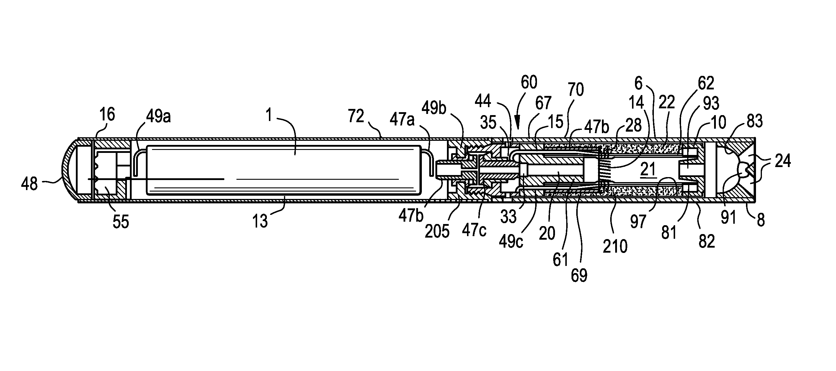
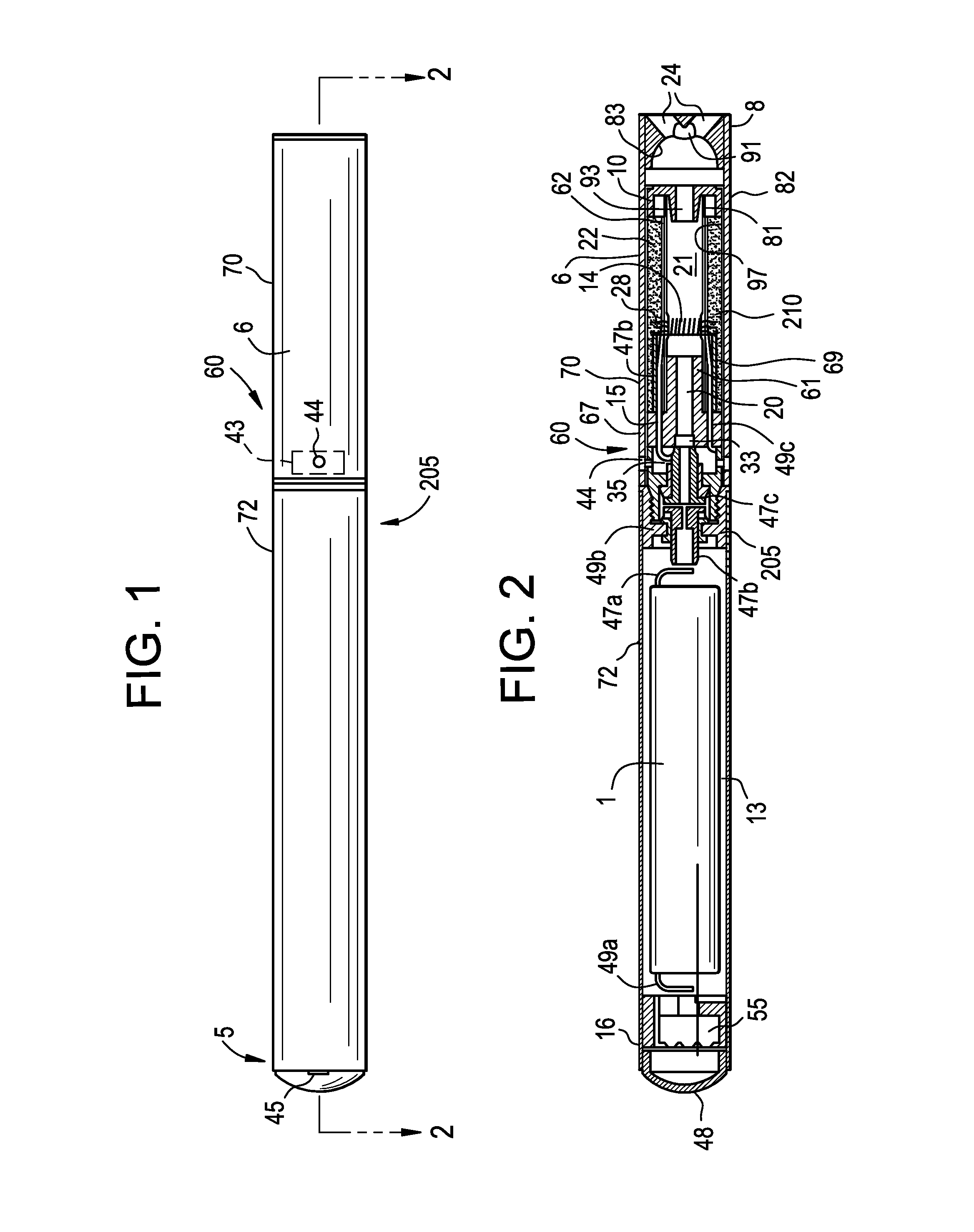
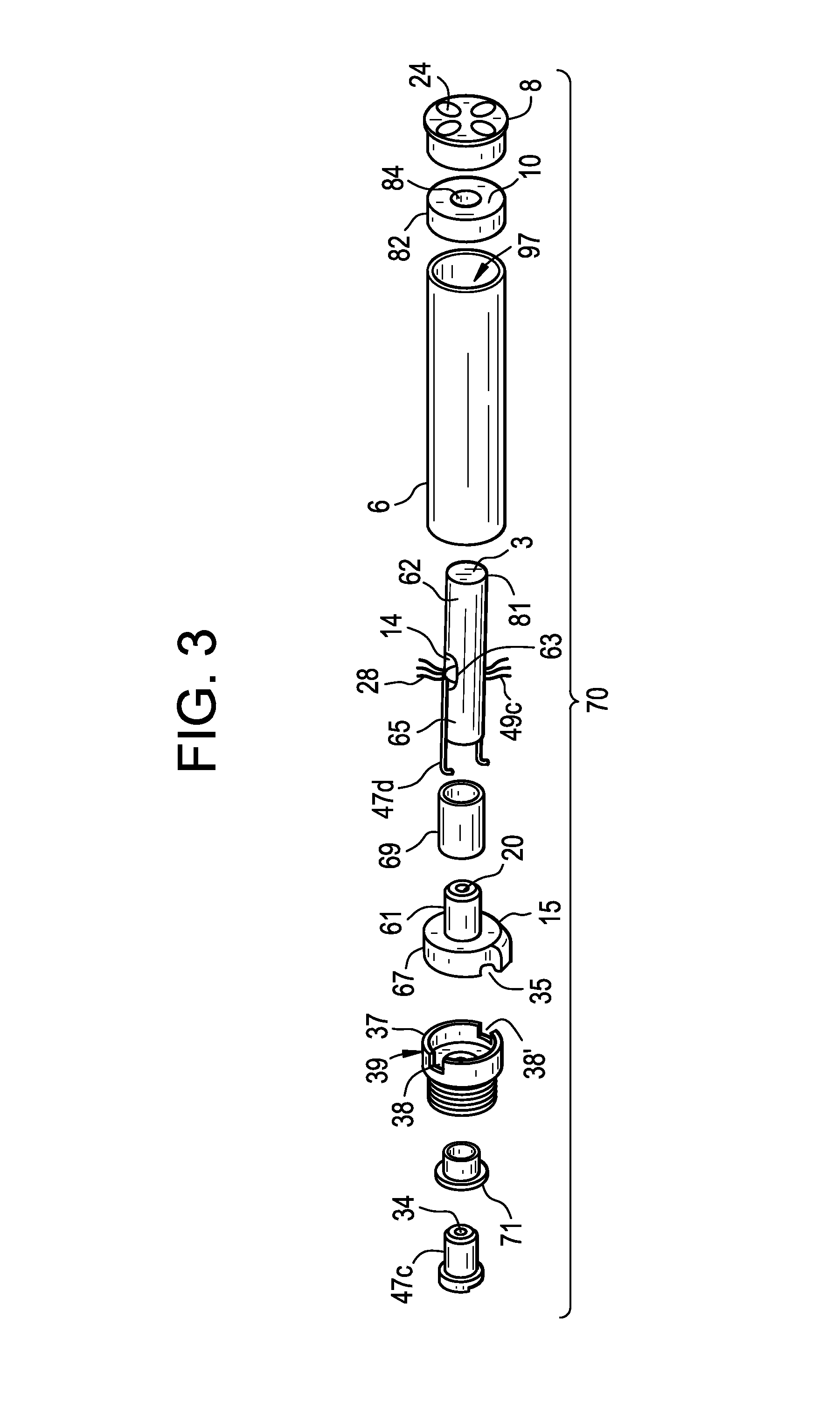
Example embodiments relate to a cartomizer including a housing, a fluid reservoir, configured to store an e-fluid, in the housing, a vaporizer configured to vaporize the e-fluid, the vaporizer including a heater having at least one end portion connected to an electrical lead wire, and a sleeve covering the connection between the end portion of the heater and the electrical lead wire.

Description

BACKGROUND[0001]Field[0002]The present disclosure relates to an electronic vaping or e-vaping device operable to deliver liquid from a liquid supply source to a vaporizor.[0003]Description of Related Art[0004]An e-vaping device includes a heater element which vaporizes liquid material to produce a “vapor.” The heater element includes a resistive heater coil, with a wick extending therethrough.[0005]The e-vaping device includes a power supply, such as a battery, arranged in the device. More specifically, an electrical connection between an anode of the battery and the heating coil is established through a battery anode connection post, an anode post of a cartridge, and an electrical lead connecting the anode post with an electrical lead of the heating coil. Likewise, an electrical connection between a cathode of the battery and the heating coil is established through a cathode connection fixture, a cathode connector piece, and an electrical lead. The electrical leads and the heater c...

Claims


Application Information

Patent Timeline
Patent Type & Authority Applications(United States)
IPC IPC(8): H05B3/80H05B3/00A24F40/10A24F40/40
CPCH05B3/00H05B3/80H05B3/06H05B2203/014H05B2203/021H05B3/12A24F40/10A24F40/40
Inventor TUCKER, CHRISTOPHER S.BURTON, DOUGLAS A.
Owner AKRIA CLIENT SERVICES LLC
Learn More