
Image stabilization apparatus that reduces blurring of subject image and optical device

a technology of image stabilization and subject image, applied in the field can solve problems such as unstable performance of image stabilization apparatus, and achieve the effect of reducing the range of initial position of the rolling member and reducing the variation of surface accuracy of the rolling surfa

Inactive Publication Date: 2016-12-08
CANON KK
View PDF14 Cites 4 Cited by
  • Summary
  • Abstract
  • Description
  • Claims
  • Application Information

AI Technical Summary

Benefits of technology

The present invention is a device that stabilizes images by moving a part of the device in a way that reduces shaking. The device uses rollers to create smooth motion. The invention reduces variations in the performance of the device caused by the roughness of the surface where the rollers move. This will make the device work better and smoother no matter what kind of surface it is placed on.

Problems solved by technology

When the range of the initial range is wide, an image stabilizing operation tends to be affected by the surface accuracy of a rolling surface for the ball, and performance of the image stabilization apparatus may be unstable.

Method used


Image

  • Image stabilization apparatus that reduces blurring of subject image and optical device
  • Image stabilization apparatus that reduces blurring of subject image and optical device
  • Image stabilization apparatus that reduces blurring of subject image and optical device

Examples


Embodiment Construction

[0023]Hereafter, embodiments of the present invention will be described with reference to the drawings.

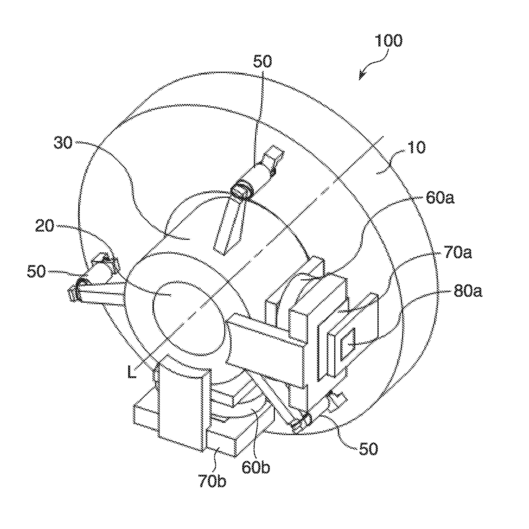
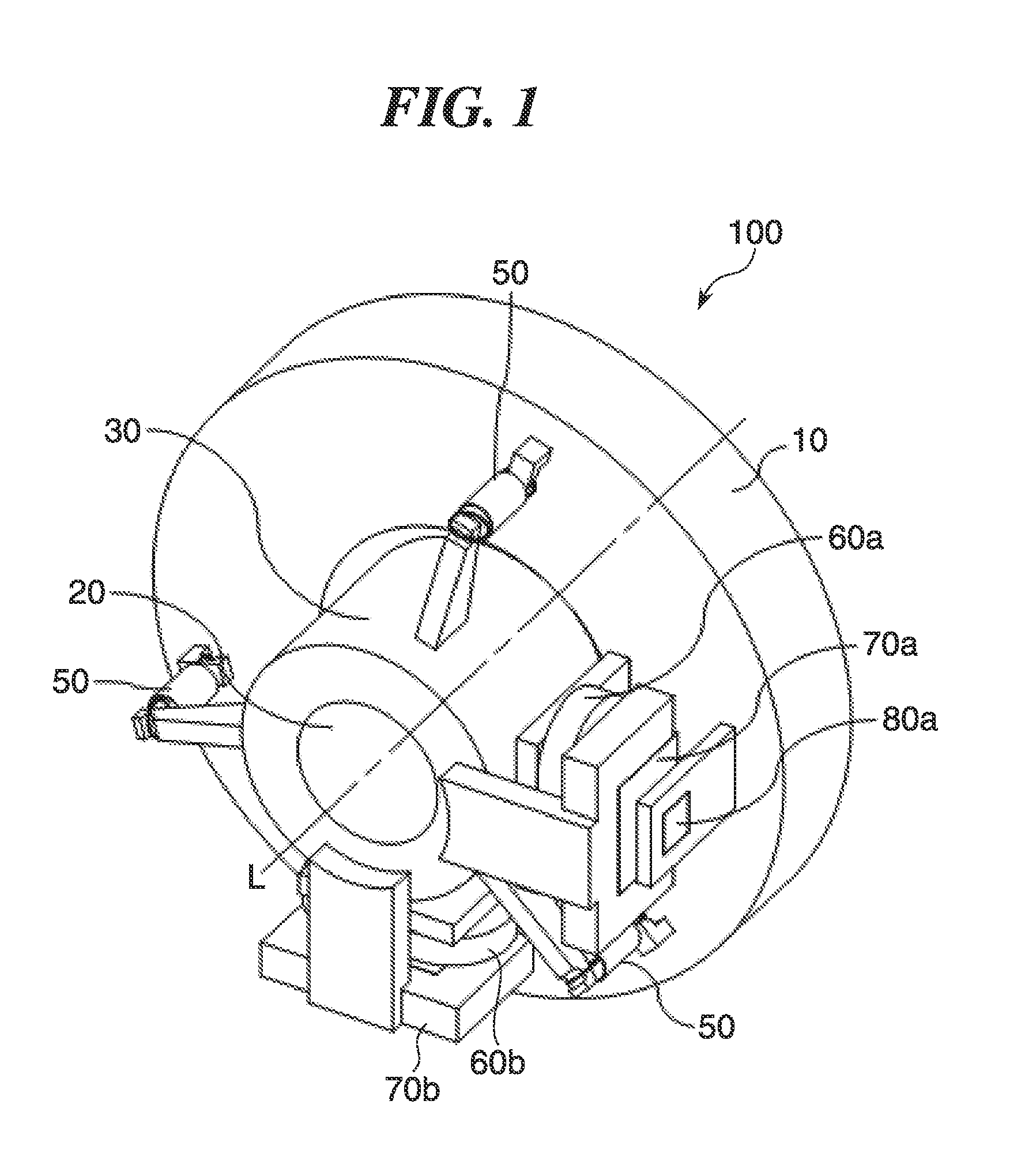
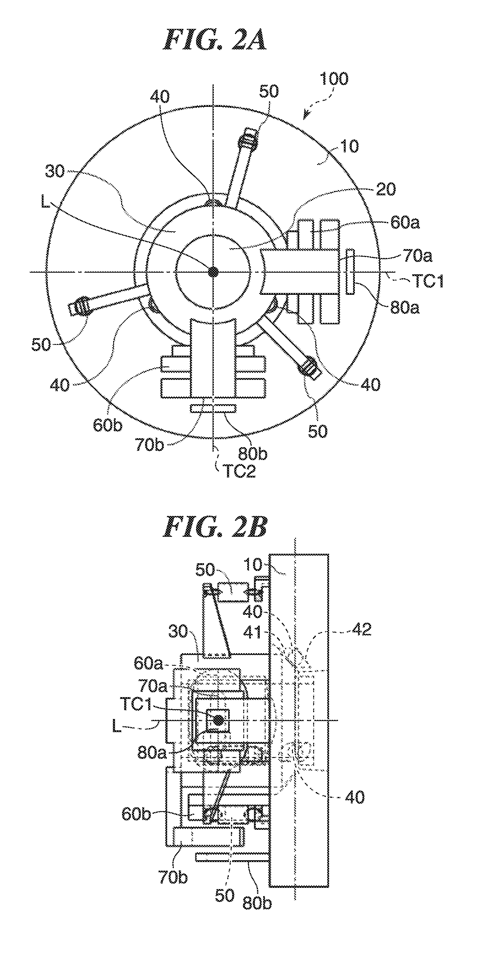
[0024]FIG. 1 is a perspective view showing an image stabilization apparatus 100 according to a first embodiment of the present invention as seen from front (subject side). FIG. 2A is a view showing the image stabilization apparatus 100 as seen from front in a direction of an optical axis, and FIG. 2B is a right side view of FIG. 2A.

[0025]Referring to FIGS. 1, 2A, and 2B, the image stabilization apparatus 100 according to the present embodiment has a movable unit 30 which holds an optical element 20 such as a lens. The movable unit 30 is rotatable about two rotational axes TC1 and TC2 which are not parallel to (for example, perpendicular to) an optical axis L of a lens barrel, not shown. Here, the rotational axis TC1 corresponds to an exemplary first rotational axis of the present invention, and the rotational axis TC2 corresponds to an exemplary second rotational axis of the presen...


PUM


Abstract

An image stabilization apparatus which reduces variations in performance with surface accuracy of a rolling surface for rolling members. A movable unit holds an optical element and is rotatable about a first rotational axis perpendicular to an optical axis of the optical element and a second rotational axis perpendicular to the optical axis and the first formational axis through rolling of the rolling members. With the second rotational axis coinciding with a center of the rolling surface, a first ratio of the first moving range of the rolling members to the first rotational range of the movable unit is smaller than a second ratio of the second moving range of the rolling members to the second rotational range of the movable unit.

Description

BACKGROUND OF THE INVENTION[0001]Field of the Invention[0002]The present invention relates to an image stabilization apparatus to, for example, reduce blurring of a subject image and an optical device.[0003]Description of the Related Art[0004]Some lens barrels of digital cameras or the like have an image stabilization apparatus that reduces blurring of a subject image, which is formed on a light-incident surface, by moving all or a part of a shooting optical system in response to externally-applied vibration.[0005]For example, for an image stabilization apparatus constructed such that a movable unit which holds a corrective lens moves on a plane perpendicular to an optical axis, there has been proposed a technique to set a range over which a restriction unit restricts movement of a ball sandwiched between a fixed unit and the movable unit to a half of a maximum amount of movement of the movable unit.[0006]According to this proposal, when the movable unit lies at a central position, ...

Claims


Application Information

Patent Timeline
IPC IPC(8): G02B27/64H04N5/232G02B7/02
CPCG02B27/646H04N5/23248G02B7/023G02B27/64H04N23/68
Inventor IZUMI, MITSUHIRO
Owner CANON KK
Learn More