
Retractable lanyard lock mechanism

a technology of locking mechanism and retractable lanyard, which is applied in the direction of life-saving devices, safety belts, etc., can solve the problems of substantial “fail” safe locking mechanism, serious injury or even death of users, and the component of lanyard locking may becom

Active Publication Date: 2016-12-01
RELIANCE INDUSTRIES LIMITED
View PDF0 Cites 9 Cited by
  • Summary
  • Abstract
  • Description
  • Claims
  • Application Information

AI Technical Summary

Benefits of technology

The retractable described in this patent uses a displacement locking mechanism, which ensures the pawl engages the sperrid to stop rotation of the drum during a fall. The pawl must be able to pivot freely under just the force of the retraction spring, or it cannot move out of the way of the sperrid tip. If there is any internal damage to the retractable, the pawl will not move and the retractable will be locked up, preventing it from being used. This ensures that the retractable works safely and reliably.

Problems solved by technology

However, when the lifeline is pulled from the retractable at a very rapid rate such as when a user is falling, a clutch or shock absorber or other similar clutch lock mechanism in, or associated with, the retractable reel or drum will automatically engage and slow and / or stop the reel or drum from rotating to slow or stop the unwinding of the lifeline.
This results in a situation in which the lanyard locking components may become frozen in a non-engaging position that can allow the lifeline to freely unwind from the lanyard drum without stopping.
Should a user be attached to a lanyard in this condition and fall, the lifeline may continue to discharge to its full length, thereby causing serious injury or even death to the user.
In this way, the locking mechanism is substantially “fail safe”, in that the disclosed locking mechanism will substantially ensure that the locking mechanism will result in the pawl engaging the sperrad to stop rotation of the drum during a fall.
The loss of a pawl spring, contamination restricting the return rotation of the pawl or sperrad, or physical damage that restricts pawl rotation will result in lockup of the retractable.
Thus, if a worker pulls on the retractable cable and it will not come out of the retractable, the retractable is informing the worker that it has internal damage.
In other words, if the retractable is damaged in any way, it prevents the worker from being able to use it.

Method used


Image

  • Retractable lanyard lock mechanism
  • Retractable lanyard lock mechanism
  • Retractable lanyard lock mechanism

Examples


Embodiment Construction

[0033]While the invention will be described and disclosed in connection with certain preferred embodiments, the description is not intended to limit the claimed invention to the specific embodiments shown and described herein, but rather the claimed invention is intended to cover all alternative embodiments and modifications that fall within the spirit and scope of the invention as defined by the claims included herein as well as any equivalents of the disclosed and claimed invention.

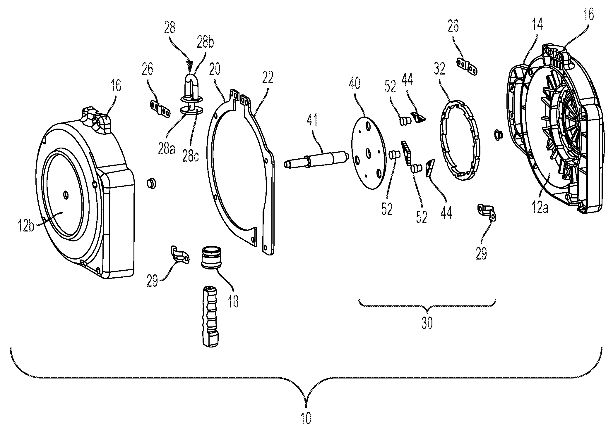
[0034]A retractable 10, shown in FIGS. 1 and 2, has a housing comprised of two housing halves 12a,b. The housing halves, when joined, define an internal area in which a drum (not shown) is rotatably mounted. As is known, the lifeline is wound about the drum to be extended from, and retracted onto, the drum. Only one half of the housing is visible in FIG. 2, and then from an interior view. The housing further defines a handle 14 to facilitate grasping of the retractable, an attachment point 16 which rece...


PUM


Abstract

A clutch lock mechanism for a retractable lanyard includes a pivotal pawl with an engagement end and a sperrad or sperrad ring having teeth which face toward the engagement end of the pawl. One of the sperrad and the pawls are circumferentially fixed, and the other moves relative to the former. The pawl is pivotal movable between an engagement position in which the pawl engagement end within an annular ring defined on one side by the tips of the sperrad teeth and on the other side by the roots of the sperrad teeth and a non-engagement position in which the pawl engagement end is not within the engagement zone. The sperrad and the pawl are in contact with each other, such that, as one moves relative to the other, the engagement end of the pawl is positively moved into the engagement zone without the need to rely on centrifugal forces. Additionally, a housing for the retractable is made from, for example, plastic, and is provided with a reinforcement, such that the reinforcement bears the forces in a fall, thereby allowing the housing to be made from lightweight, non-structural materials.

Description

CROSS REFERENCE TO RELATED APPLICATIONS[0001]This application claims priority to U.S. App. No. 62 / 168,106 filed May 29, 2015, entitled “Retractable Lanyard Lock Mechanism.” In addition, this application is related to application Ser. No. 14 / 094,422 filed Dec. 2, 2013 which claims priority to U.S. App. No. 61 / 738,981 filed Dec. 18, 2012, and U.S. App. No. 61 / 732,400 filed Dec. 2, 2012. All of said applications are incorporated herein by reference.STATEMENT REGARDING FEDERALLY SPONSORED RESEARCH OR DEVELOPMENT[0002]Not applicable.BACKGROUND OF THE INVENTION[0003]This invention relates generally to retractable lanyards, and more particularly to a mechanical clutch locking mechanism for a retractable lanyard that is configured to further ensure that the fall arrest lanyard will not fail to lock in a fall situation even if the locking components become fouled or frozen in place.[0004]Self-retracting lanyards (retractables) are safety devices that are designed to reduce the risks of a fal...

Claims


Application Information

Patent Timeline
Patent Type & Authority Applications(United States)
IPC IPC(8): A62B35/00
CPCA62B35/0043A62B35/0093
Inventor CHOATE, GARY E.HENN, DAN
Owner RELIANCE INDUSTRIES LIMITED
Learn More