
Built-in synchronizer and shift control mechanism thereof

a technology of synchronizer and shift control mechanism, which is applied in the direction of gearing control, gearing element, clutch, etc., can solve the problems of poor gear shift smoothness, increased size and weight of the transmission, and economics of the vehicle, so as to reduce the axial size of the transmission. , the effect of compact arrangemen

Inactive Publication Date: 2016-11-24
ZHAO LIANGHONG
View PDF4 Cites 5 Cited by
  • Summary
  • Abstract
  • Description
  • Claims
  • Application Information

AI Technical Summary

Benefits of technology

The present invention provides a transmission with a built-in synchronizer and shift control mechanism that are more compact and integrated, reducing the size and weight of the transmission and manufacture cost. The number of gear pairs can be increased, improving the vehicle's dynamic property and economy, while gear shift smoothness is also improved.

Problems solved by technology

If the number of gears is increased in case of not increasing the number of transmission shafts, it is possible to result in increased axial size of the transmission; and if the number of gears is increased in case of increasing the number of transmission shafts, it is possible to result in increased radial size of the transmission, and these both results will result in increased size and weight of the transmission; and therefore, owing to a smaller number of gears of the transmission of the existing transverse engined and front-wheel drive vehicle, the dynamic property and the economy of the vehicle will be not ideal, with relatively poor gear shift smoothness of the transmission.

Method used


Image

  • Built-in synchronizer and shift control mechanism thereof
  • Built-in synchronizer and shift control mechanism thereof
  • Built-in synchronizer and shift control mechanism thereof

Examples


embodiment 1

[0030]FIG. 4 is an example schematic view where the built-in synchronizer is mounted in a gear transmission mechanism of a 5-speed manual transmission or a polar automated mechanical transmission (AMT for short). This example consists of three shafts (an input shaft 26, an output shaft 20 and a reverse gear shaft 25), three synchronizers (a reverse gear and first gear synchronizer 21, a second gear and third gear synchronizer 22 and a fourth gear and fifth gear synchronizer 24), and a shift control mechanism 23.

[0031]The reverse gear and first gear synchronizer 21 and the second gear and third gear synchronizer 22 are disposed on the output shaft 20, and the fourth gear and fifth gear synchronizer 24 are disposed on the input shaft 26. The shift control mechanism 23 is partially disposed outside the input shaft and the output shaft.

[0032]When some gear is used to transmit power when needed, the shift control mechanism makes the synchronizer of the corresponding gear jointed to reali...

embodiment 2

[0033]FIG. 5 shows an example in which the built-in synchronizer is mounted in a gear transmission mechanism of an 8-gear dual clutch automated transmission. In this example, a control force of the synchronizer is supplied by a hydraulic force. This example consists of four shafts (a first input shaft 40, a second input shaft 43, an output shaft 31 and a reverse gear shaft 35), five synchronizers (a first gear and third gear synchronizer 36, a second gear and fourth gear synchronizer 32, a fifth gear and seventh gear synchronizer 38, a sixth gear and eighth gear synchronizer 41 and a reverse gear synchronizer 34), and five shift control pistons (a first gear and third shift control piston 37, a second gear and fourth shift control piston 30, a fifth gear and seventh shift control piston 39, a sixth and eighth shift control piston 42 and a reverse shift control piston 33).

[0034]The first gear and third gear synchronizer 36, the second gear and fourth gear synchronizer 32 and the reve...


PUM


Abstract

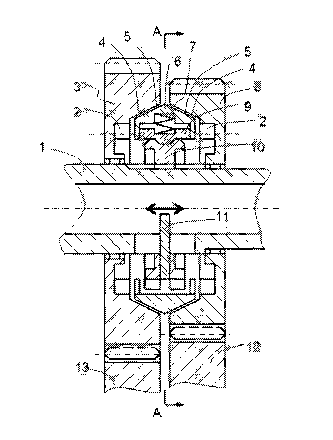
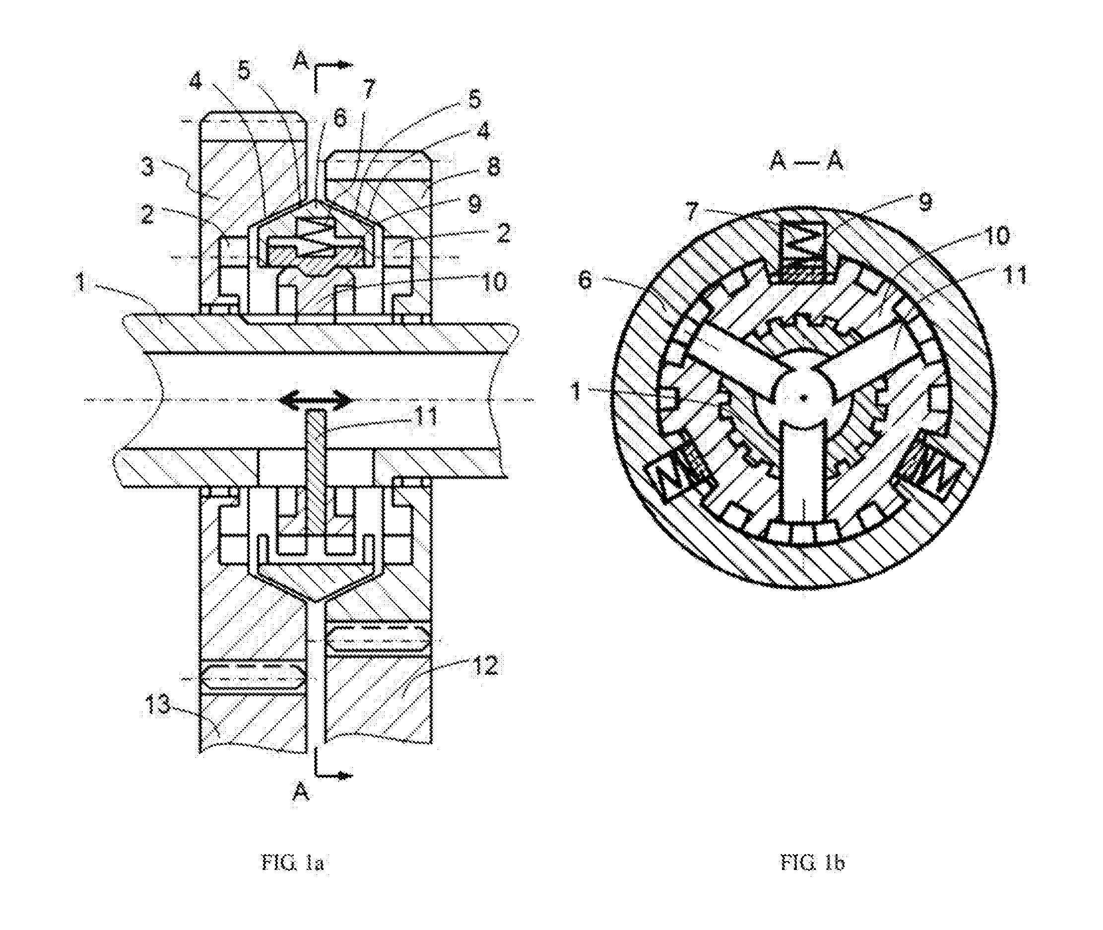
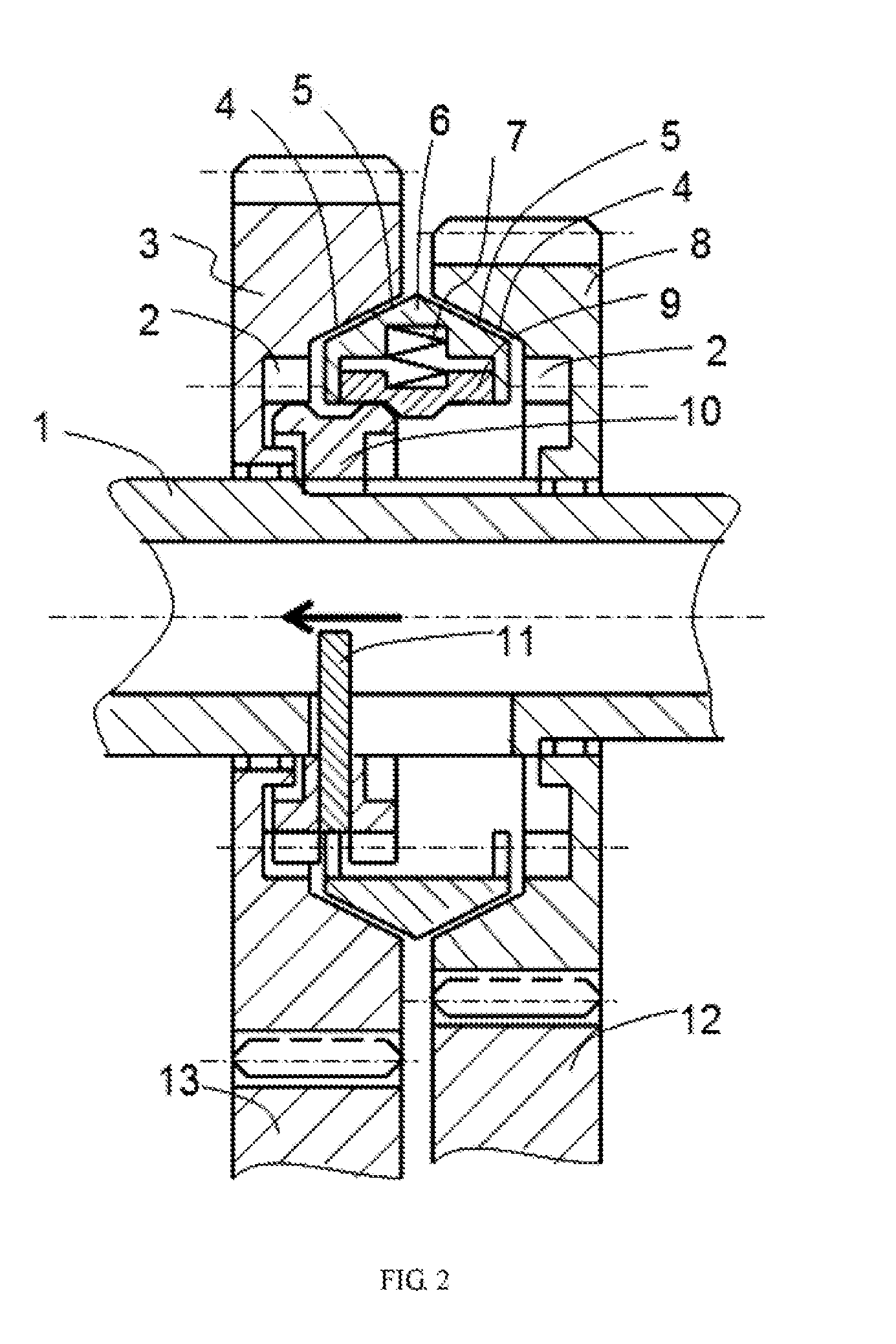
The present invention discloses a built-in synchronizer, comprising mounting shafts and gears, with the gears being sheathed on the mounting shaft; and further comprising a spline hub, a deflector rod, and a bidirectional synchronization ring. The spline hub is connected to the mounting shaft. A concave cavity is arranged on each of the gears. A side wall of each concave cavity is provided with an inner joint gear ring. A hollow shaft sleeve is disposed in the mounting shaft, and a slot hole is provided on the shaft sleeve. One end of the deflector rod is embedded into the spline hub, and the other end of the deflector rod penetrates the slot hole of the shaft sleeve and is inserted in to an inner cavity of the shaft sleeve. An outer gear ring of the spline hub is adapted to the inner joint gear ring of each of the gears. The bidirectional synchronization ring is provided among the spline hub and the side walls of the concave cavities of the gears. The built-in synchronizer has the advantages that on the basis of the existing parallel-axis gear transmission, the built-in synchronizer and a shift control mechanism thereof are adopted, such that gears in the transmission are compactly arranged, axial size of the transmission is reduced, the size and weight of the transmission is reduced accordingly, and manufacture cost is also reduced.

Description

TECHNICAL FIELD[0001]The present invention relates to the technical field of vehicle transmissions, and more specifically, to a novel synchronizer of a parallel-axis transmission, and a shift control mechanism thereof.BACKGROUND ART[0002]A synchronizer of a vehicle parallel-axis transmission is a dynamic jointing or disjointing apparatus which is located in a shift gear or between two shift gears. A synchronizer applied currently will occupy a part of axial space, such that axial size of the transmission becomes larger to influence arrangement of an engine and the transmission, particularly in a transverse engined and front-wheel drive vehicle. If the number of gears is increased in case of not increasing the number of transmission shafts, it is possible to result in increased axial size of the transmission; and if the number of gears is increased in case of increasing the number of transmission shafts, it is possible to result in increased radial size of the transmission, and these...

Claims


Application Information

Patent Timeline
Patent Type & Authority Applications(United States)
IPC IPC(8): F16H63/30F16D23/02
CPCF16H63/30F16D23/02F16H63/3023F16H63/304F16D23/06F16D2023/0618F16D2300/24F16H2063/3053F16H2063/3073F16H2063/3093F16D23/04
Inventor ZHAO, LIANGHONG
Owner ZHAO LIANGHONG
Learn More