Eureka AIR delivers breakthrough ideas for toughest innovation challenges, trusted by R&D personnel around the world.

Idling stop control device

a technology of idling stop and control device, which is applied in the direction of braking system, machine/engine, engine starter, etc., can solve the problems of driver discomfort, noise generation, and groan noise generated upon the termination of idling stop operation, so as to prevent driver from feeling

Inactive Publication Date: 2016-10-27
TOYOTA JIDOSHA KK
View PDF2 Cites 8 Cited by
  • Summary
  • Abstract
  • Description
  • Claims
  • Application Information

AI Technical Summary

Benefits of technology

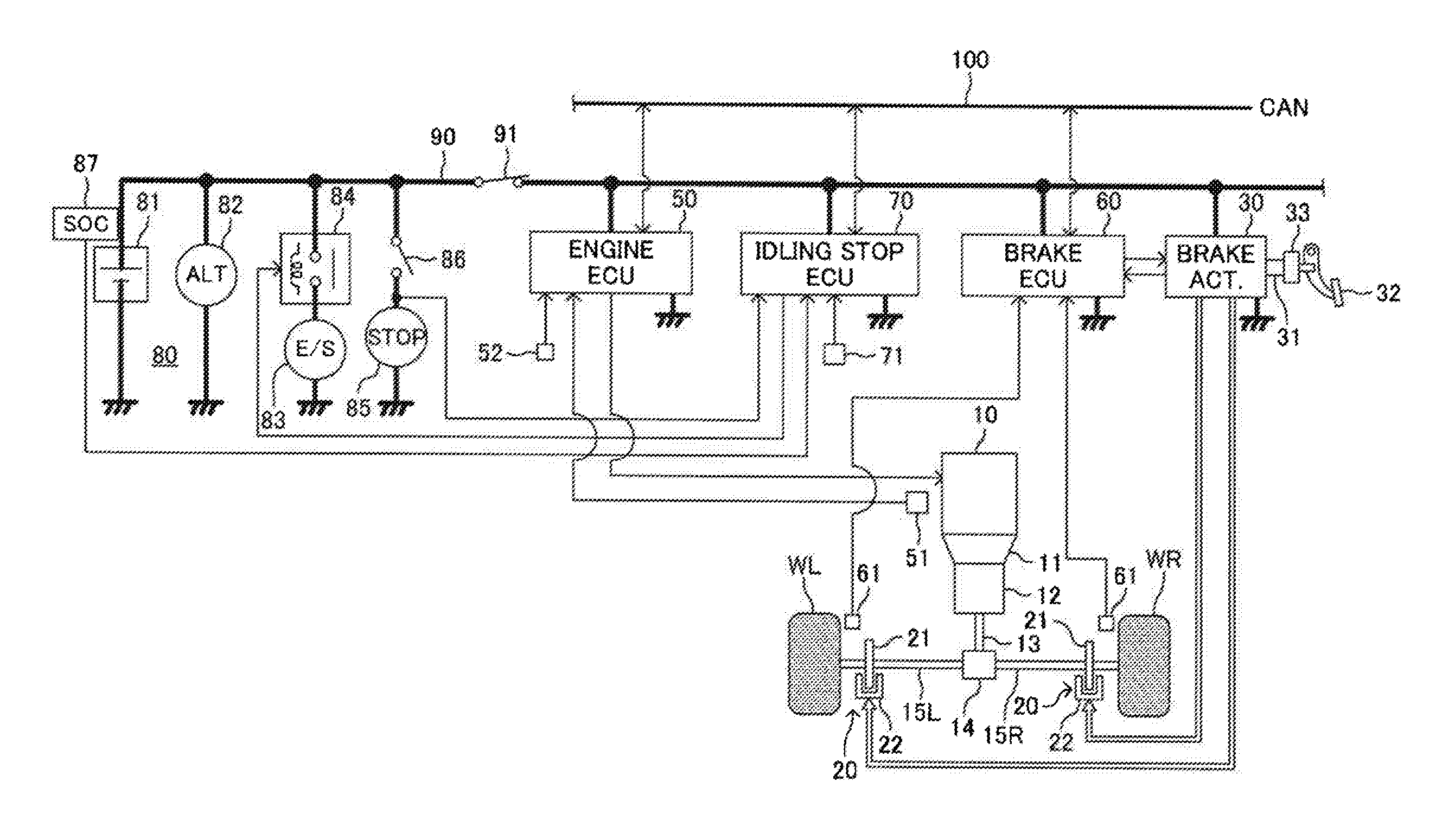
The present invention aims to decrease the discomfort felt by drivers from the groan noise caused by the engine starting up and overshooting its target idling speed. The invention achieves this by starting the decompression control at the engine-speed-decreasing-period timing, instead of the complete-explosion-achievement timing, to prevent the generation of groan noise and discomfort for the driver. The control means decreases the brake hydraulic pressure at a decreasing rate to prevent the generation of travel start shock and ensure smooth vehicle start-up. The control means also employs the engine-speed-decreasing-period timing when the time elapsing from the complete-explosion-achievement timing reaches the predetermined limit time, to ensure smooth vehicle start-up when the idling stop operation is terminated.

Problems solved by technology

In this regard, when a decompression of the brake hydraulic pressure is started at the same time as a timing when the complete explosion of the engine is detected, a noise may be generated during the decompression of the brake hydraulic pressure in a brake mechanism (for example, a disc brake mechanism) for generating a friction braking force.
The groan noise generated upon a termination of the idling stop operation is generated after the brake pedal is released.
Thus, the driver may be subject to a discomfort due to the groan noise.
Therefore, a drive torque output from the engine is increased due to the racing of the engine and thus, the groan noise is likely to be generated.
As a result, a period of the generation of the stick slip phenomena between the brake pad and the brake rotor becomes long.
Thus, the groan noise becomes large.

Method used


Image

  • Idling stop control device
  • Idling stop control device
  • Idling stop control device

Examples


modified example 1

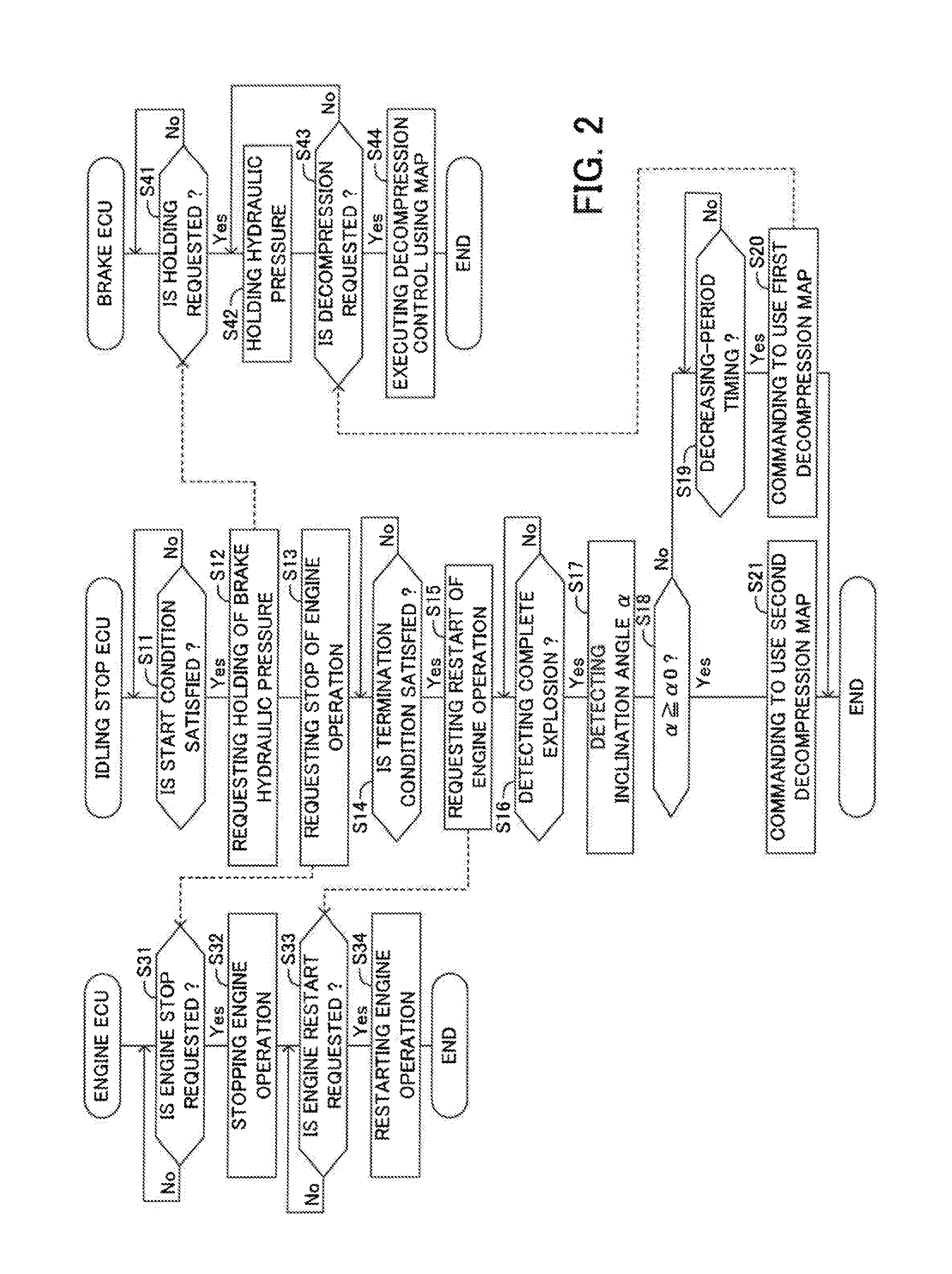
[0128]In the embodiment, it is determined whether or not the present time reaches the engine-speed-decreasing-period timing on the basis of the time elapsing from a timing when the complete explosion of the engine 10 is first detected, that is, from the complete-explosion-achievement timing (see FIG. 5). On the other hand, in this modified example 1, it is determined whether or not the present time reaches the engine-speed-decreasing-period timing on the basis of the engine speed Ne.

[0129]FIG. 6 shows a modified example of the process of the step S19. The idling stop ECU 70 determines at a step S194 whether or not the engine speed Ne is larger than a first set speed Ne1. As shown in FIG. 7, the first set speed Ne1 is previously set and is an engine speed which is expected to be detected before the present time reaches the peak time P during the racing of the engine 10 before the engine speed Ne converges on the target idling engine speed Nei*.

[0130]The idling stop ECU 70 executes th...

modified example 2

[0132]In the modified example 1, it is determined whether or not the present time reaches the engine-speed-decreasing-period timing on the basis of the engine speed Ne. In this regard, if the acquisition of the engine-speed-decreasing-period timing is delayed due to any causes, the timing of the start of the execution of the decompression control is delayed and thus, the vehicle cannot start to travel smoothly. Accordingly, in this modified example 2, when it is not determined that the present time reaches the engine-speed-decreasing-period timing on the basis of the engine speed Ne before a predetermined limit time elapses from the first detection of the complete explosion of the engine 10, it is determined that the present time reaches the engine-speed-decreasing-period timing at a timing when the predetermined limit time elapses.

[0133]For example, the idling stop ECU 70 concurrently executes a process of determining whether or not the present time reaches the engine-speed-decreas...


PUM


Abstract

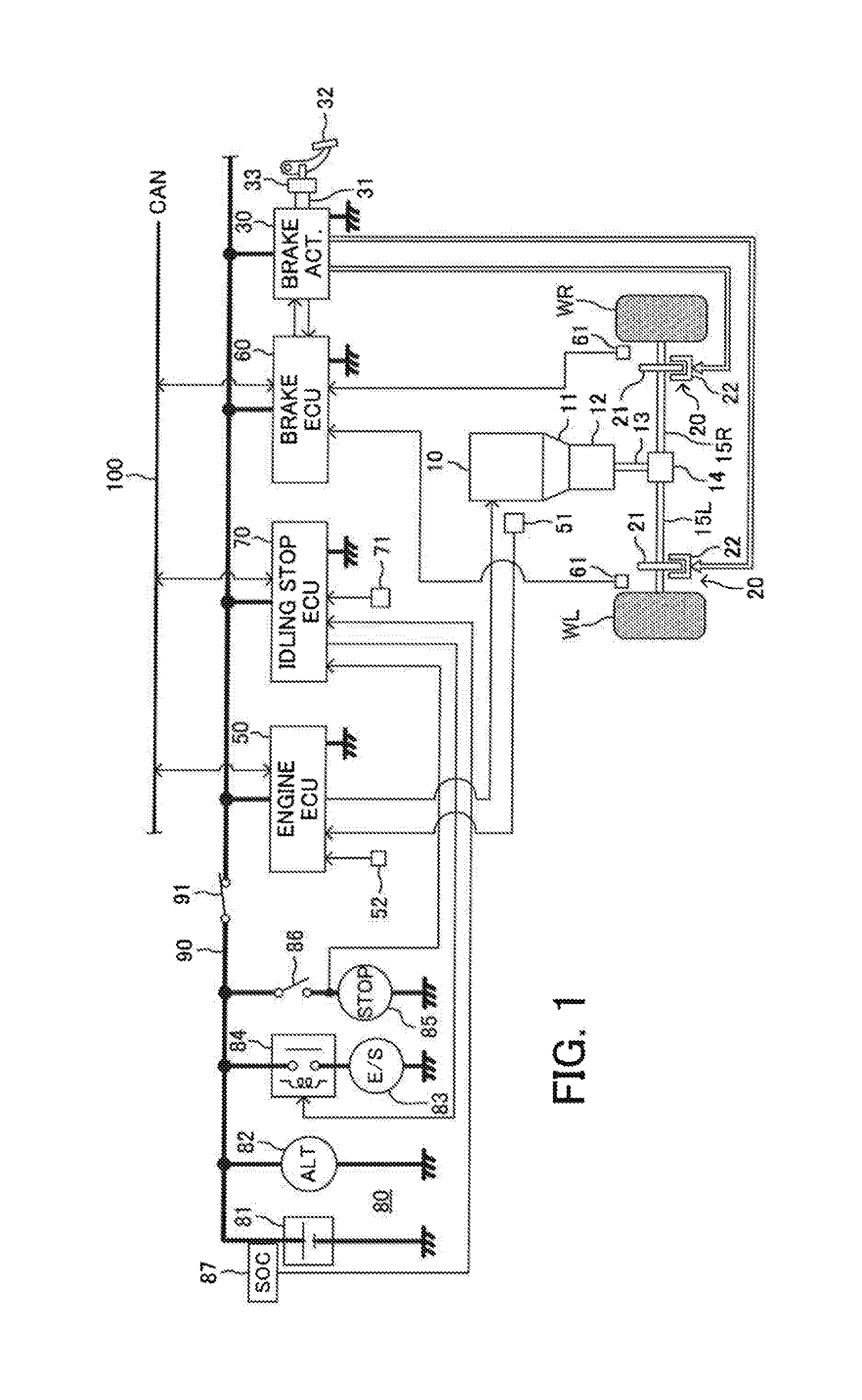
The invention relates to an idling stop control device of a vehicle. The control device starts an execution of a decompression control at an engine-speed-decreasing-period timing within an engine-speed-decreasing period when an inclination gradient is a downward slope gradient smaller than a predetermined gradient. The period corresponds to a period between a timing when the engine speed reaches a peak engine speed after the engine speed exceeds a complete explosion engine speed after the execution of the engine restart process is started and a timing when the engine speed decreases to a stable idling engine speed. On the other hand, the control device starts the execution of the decompression control at a complete-explosion-achievement timing when the inclination gradient is a downward slope gradient equal to or larger than the predetermined gradient.

Description

BACKGROUND OF THE INVENTION[0001]1. Field of the Invention[0002]The present invention relates to an idling stop control device which can reduce an amount of consumed fuel and an amount of exhaust gas by automatically stopping an operation of an internal combustion engine temporarily.[0003]2. Description of the Related Art[0004]There is known an idling stop control device for automatically stopping an engine operation, which is an operation of an internal combustion engine, when detecting that a vehicle stops on the basis of a speed of the vehicle, an operation of an brake pedal and the like. The idling stop control device restarts the engine operation when detecting that the vehicle starts to travel on the basis of a release of the brake pedal. Such an automatic stop of the engine operation will be referred to as “the idling stop”. In a vehicle that a drive torque of the engine is transmitted to vehicle wheels via a torque converter, a constant creep torque acts on the vehicle wheel...

Claims


Application Information

Patent Timeline
Patent Type & Authority Applications(United States)
IPC IPC(8): B60W30/18B60T8/50B60T8/17F02N11/08
CPCB60W30/18118F02N11/0822F02N11/0837B60W30/18054B60T8/50B60T13/66B60W10/06B60W10/196B60W2540/12B60W2550/13B60W2710/18B60T8/17B60T7/042B60T7/122B60T13/662B60T2201/06B60W10/188B60W2510/0638B60W2710/182B60W2552/15F02N2200/0807F02N2200/124F02N2300/2011Y02T10/40
Inventor TABUCHI, HIROAKI
Owner TOYOTA JIDOSHA KK
Why Eureka
Eureka Blog
Learn More