Steering Device

a steering device and steering technology, applied in the direction of steering parts, fastening means, vehicle components, etc., to achieve the effect of reducing the sound of hitting and high operability

Active Publication Date: 2016-10-13
NSK LTD
View PDF0 Cites 6 Cited by
  • Summary
  • Abstract
  • Description
  • Claims
  • Application Information

AI Technical Summary

Benefits of technology

The present invention provides a steering device that reduces the noise and impact when releasing the clamp mechanism, while still being easy to operate. This is achieved without changing the amount of lift of the cam mountains.

Problems solved by technology

However, although the steering device of Patent Literature 1 serves to reduce a sliding sound and a hitting sound occurring between the fixed cam member and the long groove for tilt-position adjustment, it does not reduce a hitting sound between a movable cam member and the fixed cam member forming a clamp mechanism.

Method used


Image

  • Steering Device
  • Steering Device
  • Steering Device

Examples


Embodiment Construction

[0033]In the following detailed description, numerous specific details are set forth in order to provide a through understanding of embodiments of the present invention. It will be, however, apparent that one or more embodiments can be practiced even without such specific details. Additionally, known structures and devices are depicted in schematic drawings in order to simplify the representations thereof.

[0034]Hereinafter, embodiments of a steering device according to the present invention will be described with reference to the drawings.

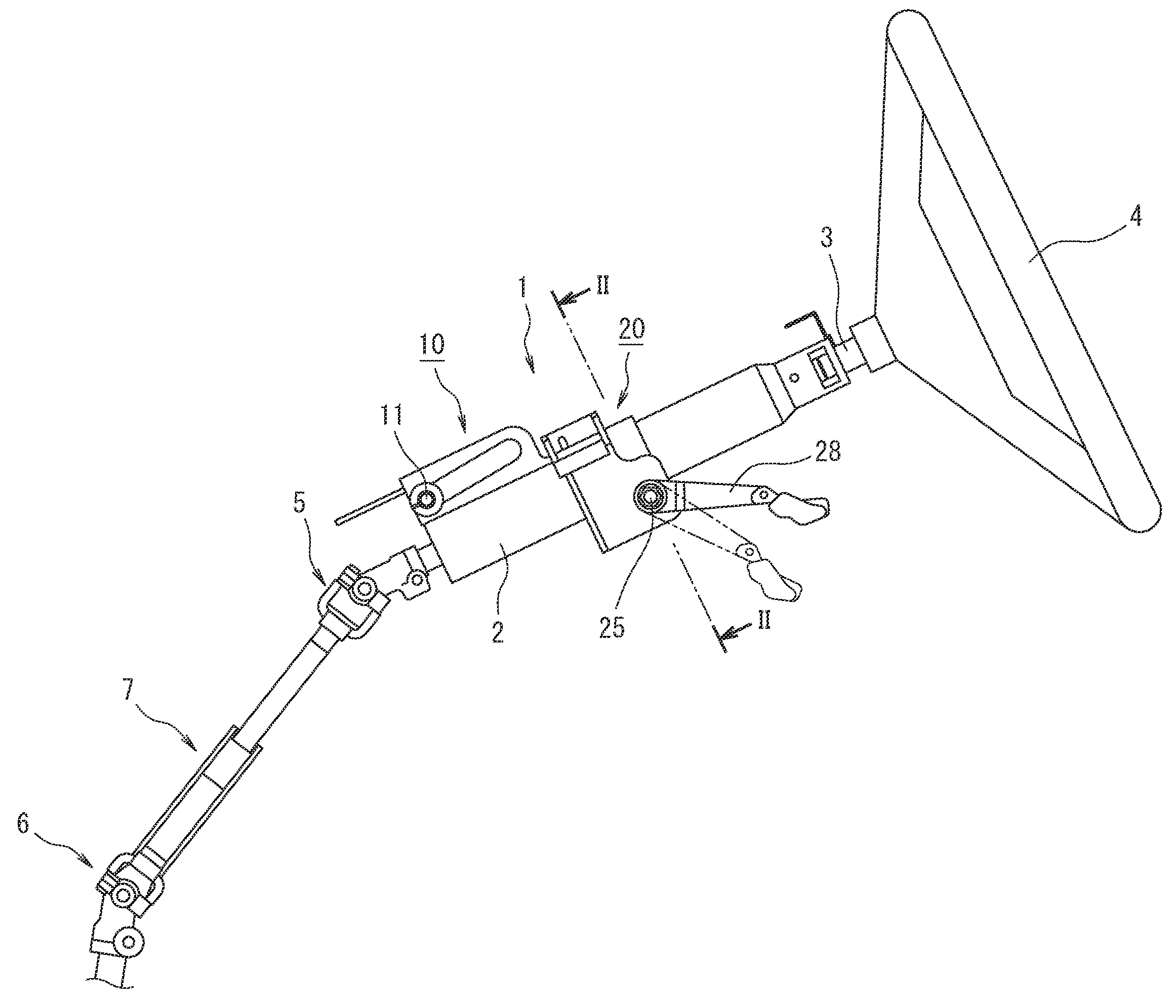
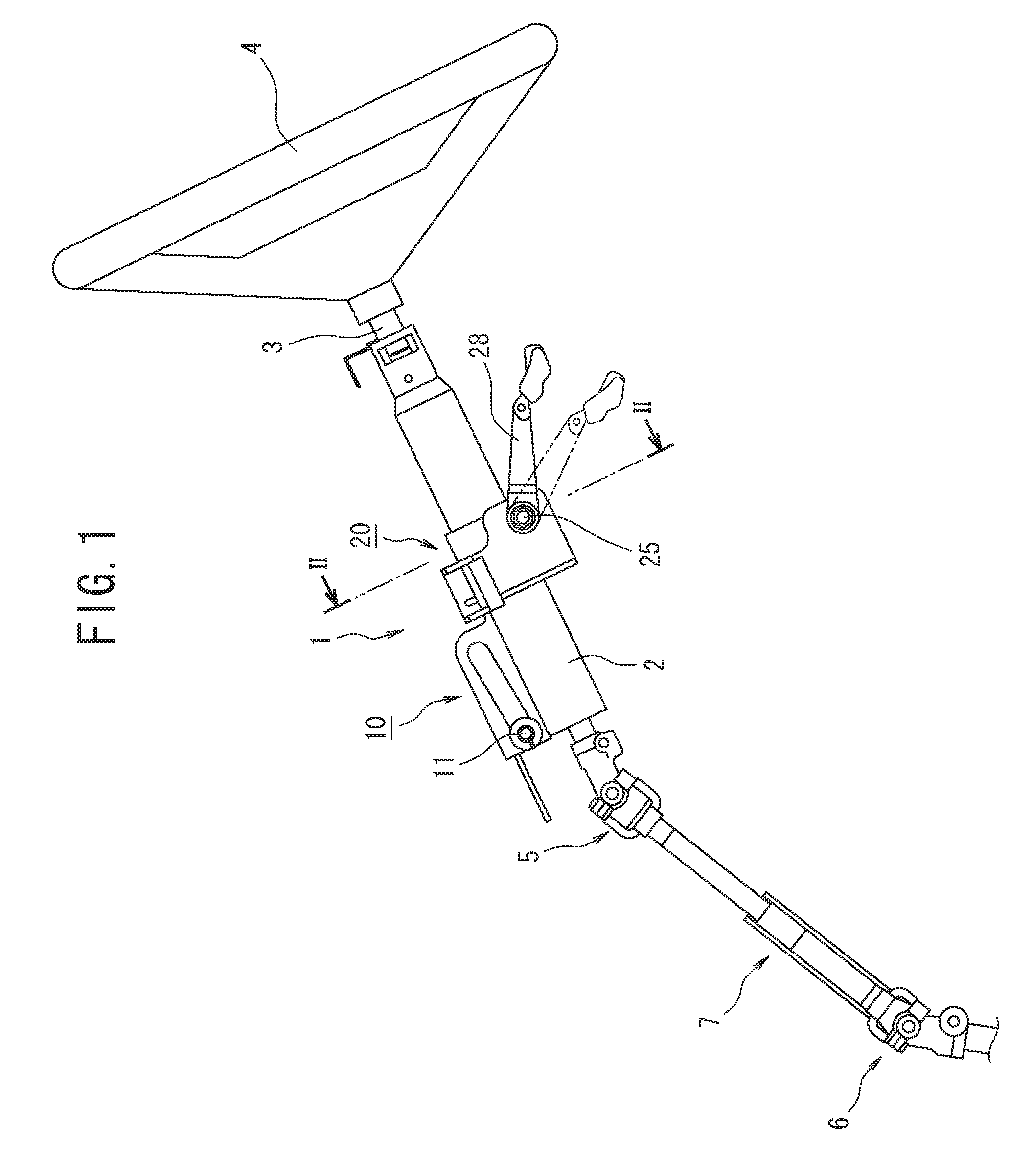
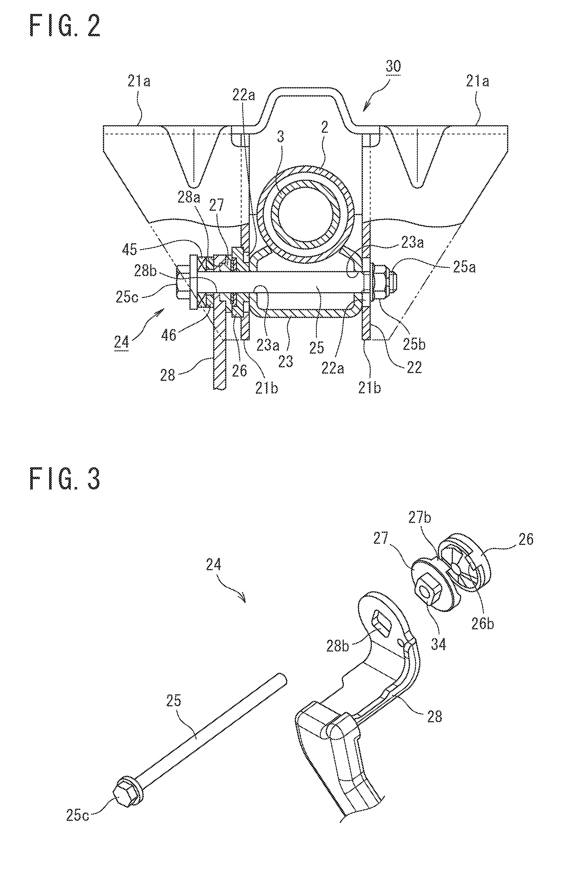
[0035]FIG. 1 is a side view of a structure in an embodiment of the steering device. In addition, FIG. 2 is a sectional view taken along line II-II of FIG. 1. Additionally, FIG. 3 is an exploded perspective view of the structure of a clamp mechanism in an embodiment of the steering device.

(Structure of Steering Device)

[0036]As depicted in FIG. 1, a steering device 1 includes a cylindrical steering column 2, a steering shaft 3 passing through the ins...


PUM


Abstract

To provide a steering device that reduces a hitting sound occurring upon release of clamping by a clamp mechanism and has high operability. A steering device including a clamp mechanism including: a shaft rod bridged across a vehicle-body attachment bracket supporting a steering column; a fixed cam member and a movable cam member configured to cause mutually opposing cam protrusions to be engaged with each other, and axially move the shaft rod in cooperation with each other; and an operation lever for moving the movable cam member. A buffer member is provided between first stopper portions of the fixed cam member and second stopper portions of the movable cam member.

Description

TECHNICAL FIELD[0001]The present invention relates to a steering device, more particularly to a steering device that can adjust a tilt position of a steering wheel according to the physical size and driving posture of a driver by supporting a steering column by a clamp mechanism using cams in a vehicle-body attachment bracket.BACKGROUND ART[0002]As such a type of steering device, a tilt fixing device for a tilt type steering column has been proposed that includes, for example, a tilt bolt that is inserted from a tilt bracket to a tilt lever and whose screw portion at one end thereof is screwed with a nut and a pair of a fixed cam member and a movable cam member that are provided on a side of the tilt bolt opposite to the nut, whose respective facing cam protrusions are engaged with each other, and whose respective bosses on back surfaces thereof are each engaged with the tilt bracket and the tilt lever, in which a clamping force is generated between the tilt bolt and the nut by oper...

Claims


Application Information

Patent Timeline
Patent Type & Authority Applications(United States)
IPC IPC(8): B62D1/184F16B2/18B62D1/187
CPCB62D1/184F16B2/185B62D1/187
Inventor TOMARU, YUUICHINARITA, NORITOMO
Owner NSK LTD
Why Eureka
Try Eureka