
Moving box automated cardio pulmonary resuscitation device

a moving box and pulmonary resuscitation technology, applied in the field of medical devices, can solve the problems of long manual cpr time, difficult control, and difficult to perform in a consistent high-quality manner, and achieve the effect of reducing non-active cpr time and speeding up initial setup

Inactive Publication Date: 2016-10-13
KONINKLJIJKE PHILIPS NV
View PDF14 Cites 13 Cited by
  • Summary
  • Abstract
  • Description
  • Claims
  • Application Information

AI Technical Summary

Benefits of technology

The patent text describes a device and method for performing automated cardiopulmonary resuscitation (CPR) that has the benefits of being easy to set up and ensuring proper contact force during the procedure. The technical effect of this invention is to improve the speed and effectiveness of CPR.

Problems solved by technology

Manual Cardio Pulmonary Resuscitation (CPR) is difficult to perform in a consistent high-quality manner.
However, consistent high quality chest compressions, is key for survival, and thus there is a strong drive to have a mechanical automated CPR device (A-CPR) to replace less reliable, frequently interrupted, difficult to control, and sometimes lengthy in duration manual CPR.
However, important issues with current A-CPR devices include long set-up times, low stability during operation of the device, as well as suggestions and clinical evidence that insufficient force is being applied for optimal performance.
However, such setup requires time before CPR can be activated, and often results in a not optimal starting height, therefore resulting in a not optimal force on the patient's chest, and hence a not optimal CPR treatment, once the CPR is activated.

Method used


Image

  • Moving box automated cardio pulmonary resuscitation device
  • Moving box automated cardio pulmonary resuscitation device
  • Moving box automated cardio pulmonary resuscitation device

Examples


Embodiment Construction

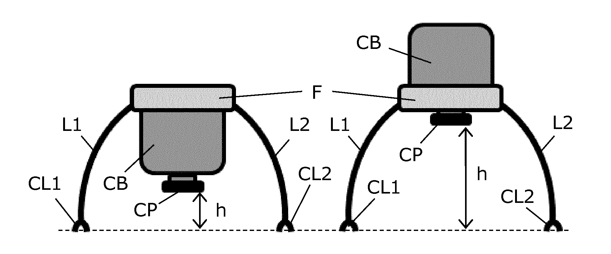
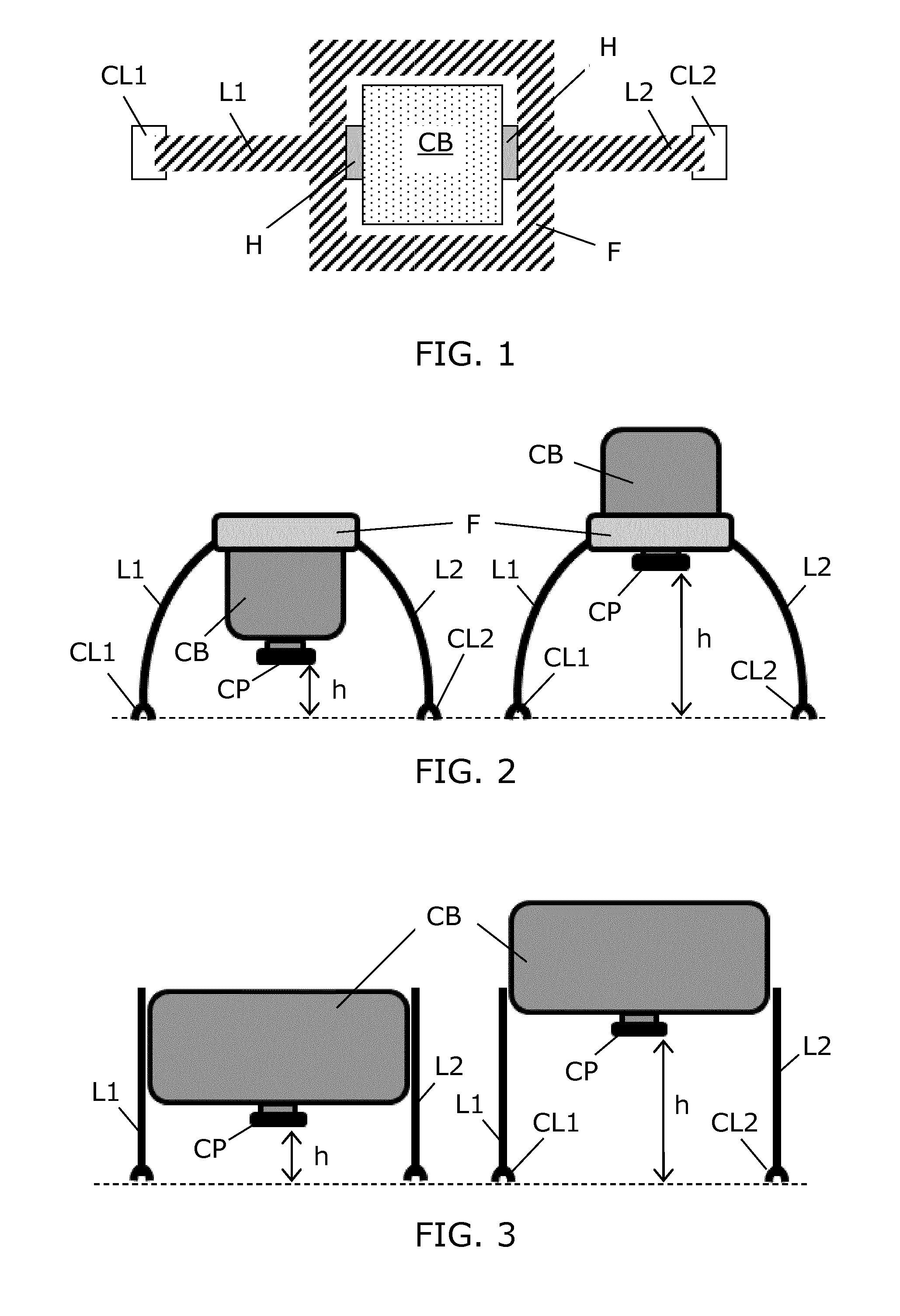
[0041]FIG. 1 illustrates a CPR device embodiment seen from above. The CPR device comprises a supporting structure with two legs L1, L2 shaped to accommodate space for the patient's thorax between the two legs L1, L2. The two legs L1, L2 are rigidly connected to a frame F. The two legs L1, L2 each has a clamp mechanism CL1, CL2 arranged for engagement with corresponding clamp mechanisms on each side of an associated backboard. Hereby, an operator can clamp the supporting structure onto a backboard, such that the supporting structure is locked in position onto the backboard. Preferably, the legs L1, L2 and the frame F are rigidly connected and shaped such that the clamp mechanisms CL1, CL2 fit onto the clamp mechanisms on the backboard. Hereby, the operator can easily position the CPR device and clamp it onto the backboard.

[0042]A compression box CB is arranged within the frame F, and the compression box CB comprises an enclosure containing a plunger mechanism, and a processor arrange...


PUM


Abstract

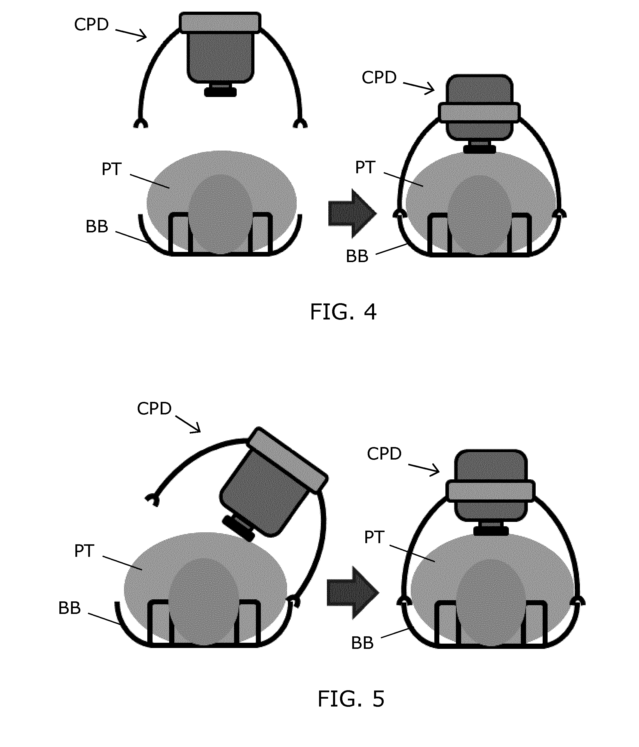
A Cardiac Pulmonary Resuscitation (CPR) device (CPD) for performing CPR on a patient (PT). A supporting structure (L1, L2, F) with two legs (L1, L2) shaped to accommodate space for the patient's (PT) thorax between them. The legs (L1, L2) have clamp mechanisms (CL1, CL2) to allow clamping onto a backboard (BB). A compression box (CB) with a plunger mechanism (PM) with a contact pad (CP) projecting downwards from the enclosure (CS), and a processor (P) for controlling the plunger mechanism (PM) to perform CPR on the patient (PT) in an automatic manner. A height adjustment mechanism (H) is used to fix a height (h) of the compression box (CB) relative to the supporting structure (L1, L2, F). The height adjustment mechanism (H) can allow the compression box (CB) to move in relation to the supporting structure (L1, L2, F) in a first operating state, by help of gravity. Hereby, the compression box (CB) can enter a height (H) where the contact pad is in contact with the patient's (PT) chest, preferably within a predetermined contact force range, upon clamping of the supporting structure (L1, L2, F) onto the backboard (BB). Hereby, the height and contact force parameters are inherently set automatically by the device, when the operator has clamped the CPR device (CPD) onto the backboard (BB). This setup task is easy for the operator, time without CPR can be saved, and CPR can be initiated with a correct contact force.

Description

FIELD OF THE INVENTION[0001]The present invention relates to the field of medical devices, more specifically to the field of automated cardio pulmonary resuscitation (ACPR) devices.BACKGROUND OF THE INVENTION[0002]Manual Cardio Pulmonary Resuscitation (CPR) is difficult to perform in a consistent high-quality manner. However, consistent high quality chest compressions, is key for survival, and thus there is a strong drive to have a mechanical automated CPR device (A-CPR) to replace less reliable, frequently interrupted, difficult to control, and sometimes lengthy in duration manual CPR. Examples of A-CPR devices are disclosed in US 2012 / 0238922 A1 and EP 1 913 924 A1, wherein US 2012 / 0238922 A1 discloses an A-CPR device that includes a plunger driven by a drive to perform a compressive massage on a patient's body, a position measuring device that measures the respective position of the plunger during its compressive massaging motion, and a holding device for the drive and the plunge...

Claims


Application Information

Patent Timeline
Patent Type & Authority Applications(United States)
IPC IPC(8): A61H31/00
CPCA61H31/006A61H2201/1207A61H2201/5061A61H2201/5058
Inventor PAULUSSEN, IGOR WILHELMUS FRANCISCUSVAN ROOIJ, WILLEM-JANWOERLEE, PIERRE HERMANUSNOORDERGRAAF, GERRIT JAN
Owner KONINKLJIJKE PHILIPS NV
Learn More