Surveillance apparatus having an optical camera and a radar sensor
a technology of optical camera and radar sensor, which is applied in the direction of individually energised antenna arrays, instruments, and reradiation, etc., can solve the problems of optical surveillance camera image impairment, optical surveillance camera vulnerability to optical system attacks, and system visual impairment, so as to increase surveillance capabilities and efficiently and flexibly monitor
- Summary
- Abstract
- Description
- Claims
- Application Information
AI Technical Summary
Benefits of technology
Problems solved by technology
Method used
Image
Examples
first embodiment
[0046]Referring now to the drawings, wherein like reference numerals designate identical or corresponding parts throughout the several views, FIG. 1 shows a surveillance apparatus 1 according to the present disclosure. It comprises an optical camera 10 configured to capture images based on received light, said optical camera 10 having a camera aperture 11. The surveillance apparatus 1 further comprises a radar sensor 20 having one or more (here three) transmitting antennas 21 (indicated by full circles) configured to emit electromagnetic radiation and one or more (here three) receiving antennas 22 (indicated by empty circles) configured to receive electromagnetic radiation. In this embodiment the antennas 21, 22 are arranged on the frame 12 of the camera 10 around the camera aperture 11. Due to their arrangement the antennas 21, 22 form a virtual antenna array, as will be explained in more detail below that is overlapping with the camera aperture 11.
[0047]The optical camera 10 is pr...
ninth embodiment
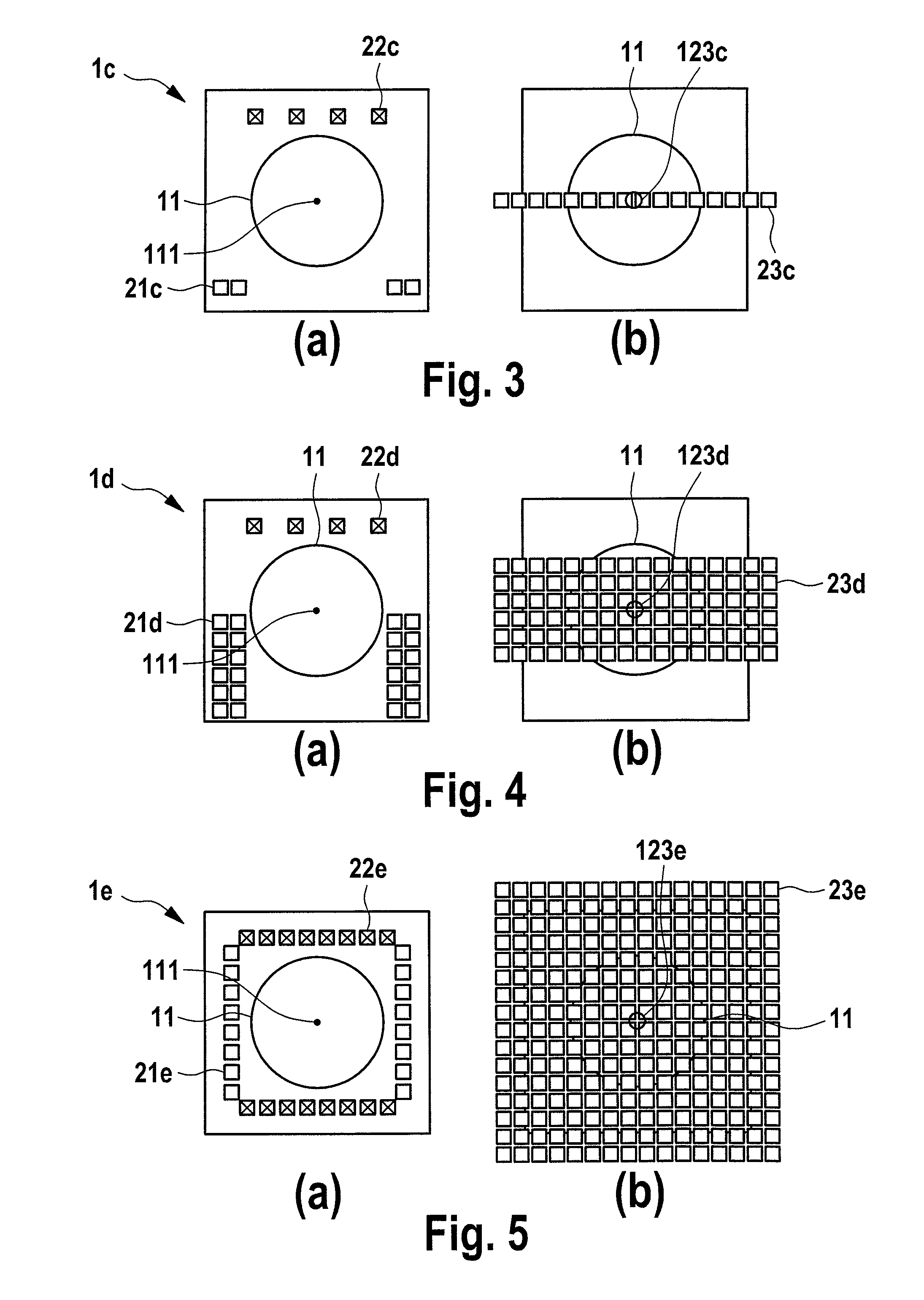
[0052]FIGS. 3 to 8 show a fourth to ninth embodiment of a surveillance apparatus 1c to 1h according to the present disclosure, particularly of the radar sensor and the camera aperture, according to which the antennas are arranged at the periphery of the camera aperture.
[0053]The embodiments 1c, 1d shown in FIGS. 3 and 4 each use a 1D MIMO antenna array having multiple Tx antennas 21c, 21d and multiple Rx antennas 22c, 22d. All the antennas cover the field of view of the optical camera. Each pair of Tx and Rx antennas is equal to one virtual antenna 23c, 23d (positioned at the spatial convolution of the real Tx and Rx antenna). All the combinations of Tx antenna and Rx antenna pairs are equal to a 1D virtual antenna array as shown in FIGS. 3(b), 4(b).
[0054]In the embodiment shown in FIG. 3(b), the center area 123c of the virtual antenna array coincides with the center area 111 (in particular the center point) of the camera aperture. In this configuration, the radar sensor and the opt...
embodiment 1
[0078]2. The surveillance apparatus ,
[0079]wherein said one or more transmitting antennas and said one or more receiving antennas are arranged on the periphery of the surveillance apparatus.
PUM
 Abstract
Description
Claims
Application Information
 - R&D
- Intellectual Property
- Life Sciences
- Materials
- Tech Scout
- Unparalleled Data Quality
- Higher Quality Content
- 60% Fewer Hallucinations
Browse by: Latest US Patents, China's latest patents, Technical Efficacy Thesaurus, Application Domain, Technology Topic, Popular Technical Reports.
© 2025 PatSnap. All rights reserved.Legal|Privacy policy|Modern Slavery Act Transparency Statement|Sitemap|About US| Contact US: help@patsnap.com


