
Connecting system for filter cassettes

a technology of connecting system and filter cassette, which is applied in the direction of membrane technology, membrane fastening, membrane technology, etc., can solve the problems of unsatisfactory leakage of filter cassette, relative difficulty in precisely and reliably adjusting contact pressure in accordance with the requirements of specific processes, and the inability of known filter cassettes to be inserted into known filter holders, so as to prevent the potential shifting of individual layers, reliably prevent the effect of medium leakage, and prevent the effect of damag

Active Publication Date: 2016-10-06
SARTORIUS STEDIM BIOTECH GMBH
View PDF3 Cites 1 Cited by
  • Summary
  • Abstract
  • Description
  • Claims
  • Application Information

AI Technical Summary

Benefits of technology

The patent describes a connector for a filter cassette that is designed to keep the individual layers of the filter sealed and prevent shifting of those layers during use. The connector has two tensioning parts that can be fixed to the end plates of the filter cassette, providing a pretensioning force that ensures a tight seal. The tensioning parts also allow for a contact-pressure force that prevents damage to the connector and further prevents leakage of the medium from the filter cassette. The connector is easy to install and cost-effective, and it ensures the filter cassette remains sealed even when it is removed from the filter holder.

Problems solved by technology

This can occasionally result in undesired leakage from the filter cassette, despite the seals arranged between the filter layers.
One disadvantage of this is the relative difficulty of precisely and reliably adjusting the contact-pressure force in accordance with the requirements of the specific process.
Another disadvantage is that these known filter cassettes cannot be inserted into the known filter holders due to their rigid bolt connections.

Method used


Image

  • Connecting system for filter cassettes
  • Connecting system for filter cassettes
  • Connecting system for filter cassettes

Examples


Embodiment Construction

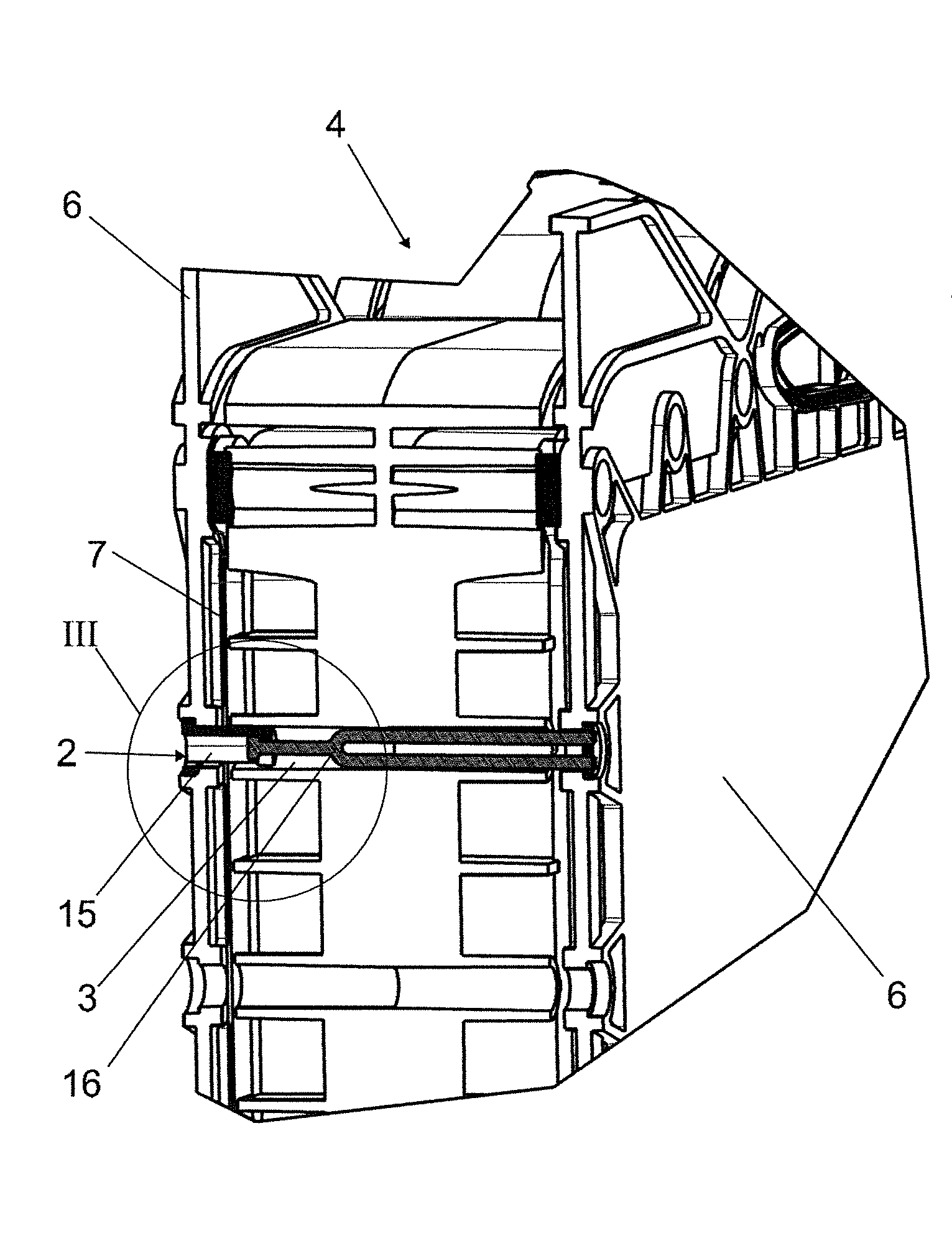
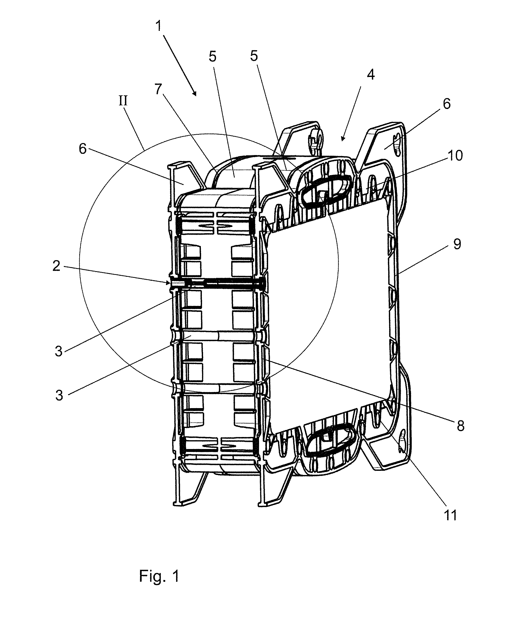
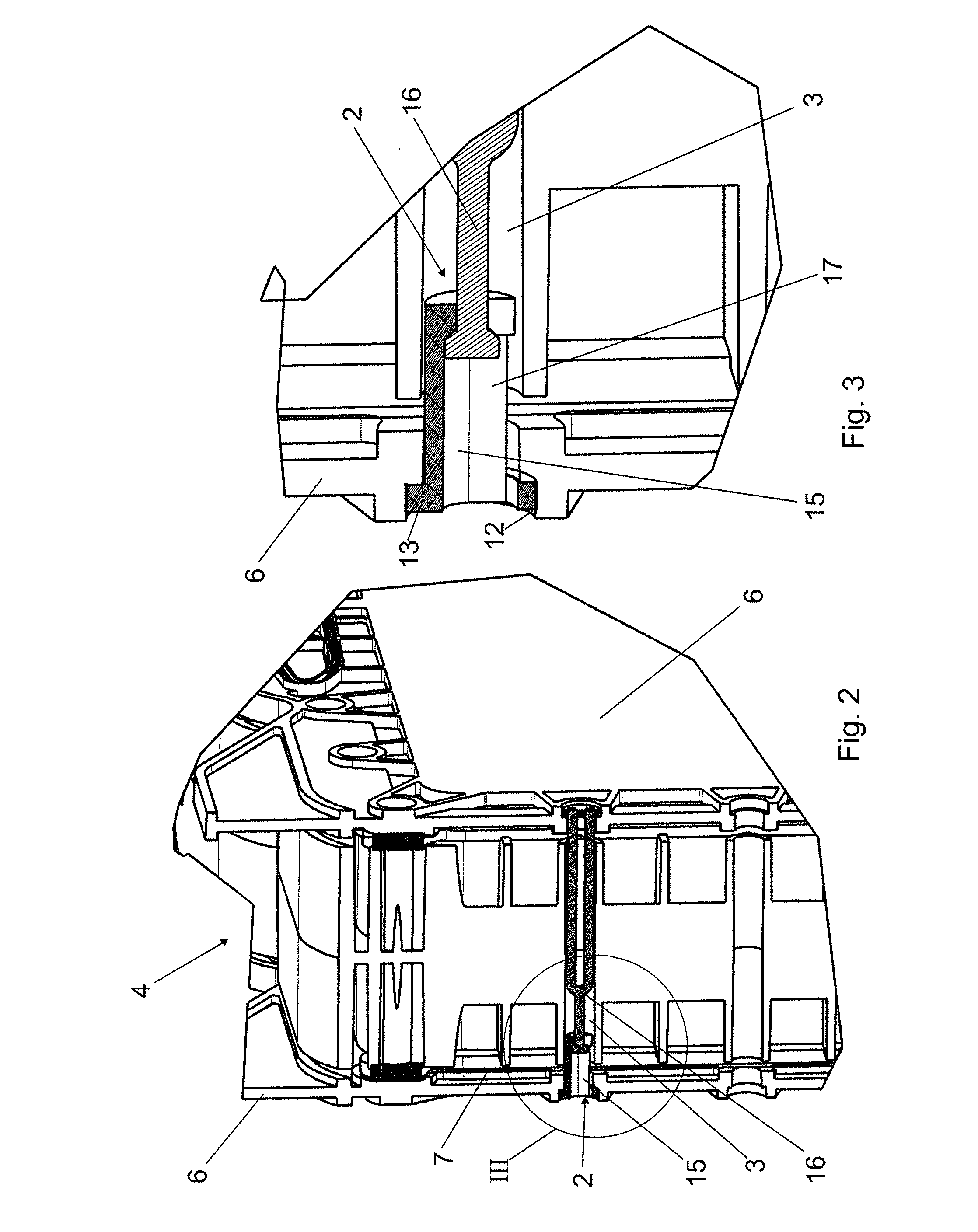
[0053]A connecting system 1 essentially comprises a plurality of connectors 2 in through-channels 3 of filter cassettes 4.

[0054]The filter cassette 4 comprises multiple filter layers 5 arranged between two end plates 6. In each case, seals 7 are arranged between the filter layers 5 and the end plates 6. The through-channels 3, which accommodate the connectors 2, run orthogonally to the end plates 6, and terminate in the edge areas of the end plates 6. The through-channels 3 transition in each case into an offset 12 in the end plates 6 to accommodate end-positioned fasteners 13, 14.

[0055]According to the exemplary embodiment in FIGS. 4 to 6, the connector 2 comprises a first tensioning part 15 and a second tensioning part 16 which engage in one another in a longitudinally displaceable manner. The first tensioning part 15 is designed as a receiving bushing 17 with a lateral opening. At its end which faces the second tensioning part 16, the receiving bushing 17 has a constriction formi...


PUM


Abstract

A connecting system (1) has at least one connector (2) for a filter cassette (4) that can be inserted into a filter holder and has filter layers (5) between two end plates (6), and seals (7) between the filter layers (5) and / or between the end plates (6) and an adjacent filter layer (5). The connector has tensioning parts that engage in one another in a longitudinally displaceable manner and that can be fixed to the end plates (6) via their ends facing away from one another. The connector exerts a pretensioning force onto the end plates (6) when it is deflected to its maximum extent. The pretensioning force pulls the end plates (6) towards the filter layers (5), and when a contact-pressure force superimposed on the pretensioning force is applied to the end plates (6), the tensioning parts can be pushed towards one another correspondingly with the end plates (6).

Description

BACKGROUND[0001]1. Field of the Invention[0002]The invention relates to a connecting system having at least one connector for a filter cassette that can be inserted into a filter holder and that has one or more filter layers arranged between two end plates, and having seals that are arranged between the filter layers and / or between the end plates and a respectively adjacent filter layer.[0003]The invention further relates to a method for applying a pretensioning force to a filter cassette that can be inserted into a filter holder and that has one or more filter layers arranged between two end plates, and having seals arranged between the filter layers and / or between the end plates and a respectively adjacent filter layer.[0004]2. Related Art[0005]Filter cassettes, such as those used for purification processes using membrane adsorbers or for filtration processes, such as deep-bed filtration, ultra-filtration and micro-filtration, consist of one or more filter layers arranged between ...

Claims


Application Information

Patent Timeline
Patent Type & Authority Applications(United States)
IPC IPC(8): B01D63/08F16B5/06B01D65/00
CPCB01D63/082B01D2313/025F16B5/0642B01D65/00B01D2313/02F16B5/065B01D63/0822
Inventor KRUMBEIN, THOMASWEISSHAAR, STEFANBATES, MICHAEL
Owner SARTORIUS STEDIM BIOTECH GMBH
Learn More