Ergonomic handpiece for laparoscopic and open surgery
a laparoscopic and open surgery technology, applied in the field of surgical tools, can solve the problems of physical constraints on the surgeon's ability to operate freely, and difficulty in accurate control
- Summary
- Abstract
- Description
- Claims
- Application Information
AI Technical Summary
Benefits of technology
Problems solved by technology
Method used
Image
Examples
fourth embodiment
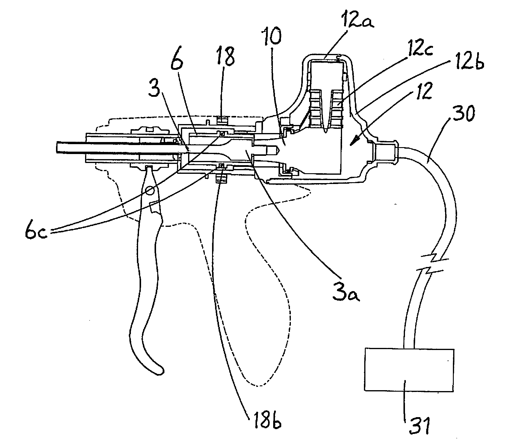
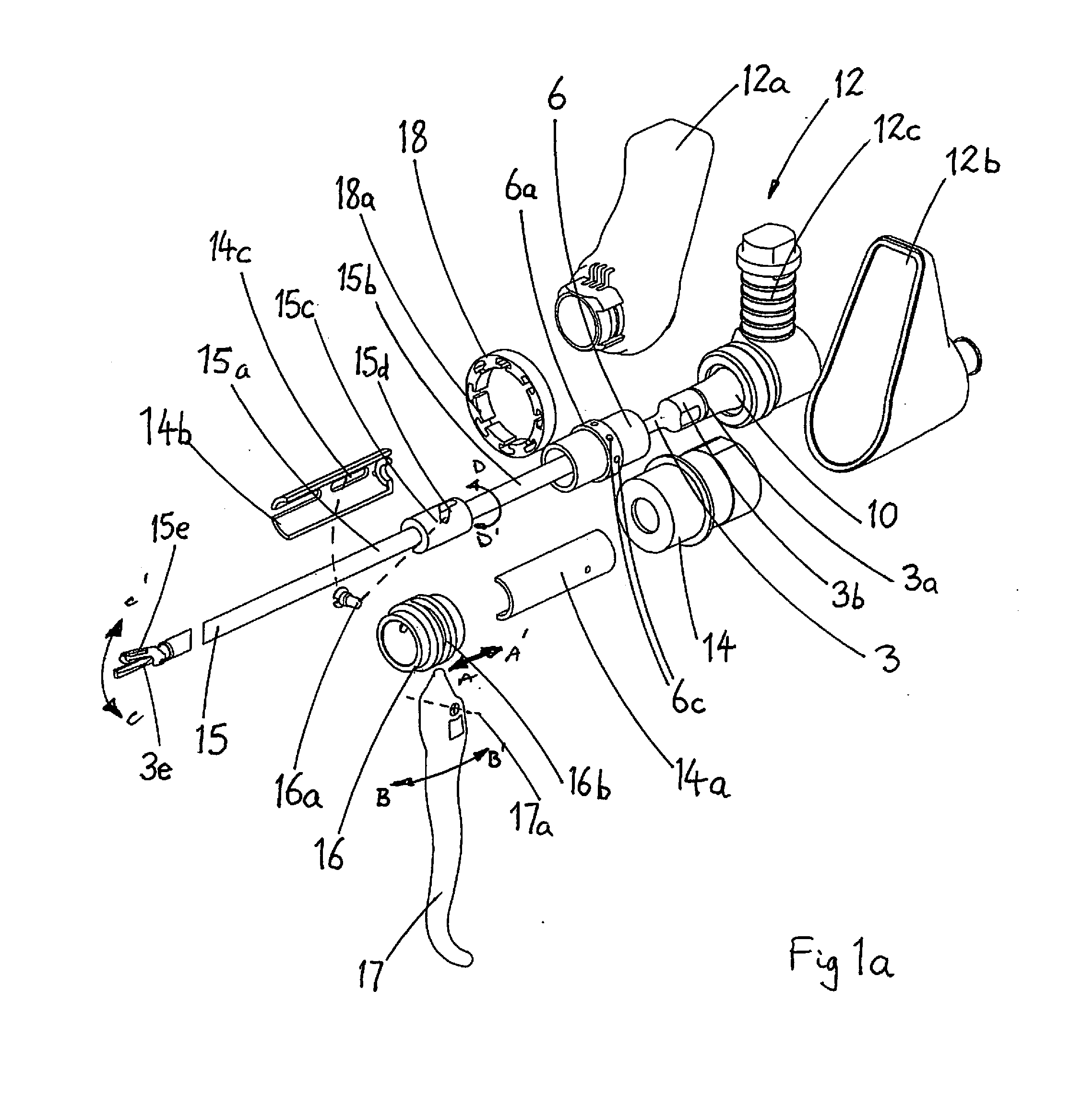
[0093]Furthermore, any of the above structures may be mounted at different locations within a surgical instrument, in order to effect the required rotation, as will be described below and shown in FIG. 5. In this fourth embodiment, a distal portion of the drive assembly of the handpiece of the tool comprises fixed stator windings 40, mounted to a manually-graspable handle 5 of the tool, while magnetic rotor elements 41 are attached to a distally-extending handpiece member 2 (which may comprise the waveguide 3 or an equivalent energy transmission member) and a proximally-extending transducer 12 through a connecting mechanism 45. The member 2, the magnetic rotor elements 41, the connecting mechanism 45 and the transducer 12 may thus be rotated about a longitudinal axis in the sense of arrow 42, relative to the handle 5 and a remainder of the casing 1 of the handpiece.
[0094]Alternatively, electromagnetic elements 50 may be incorporated into the casing 12a, 12b of the transducer 12, and...
second embodiment
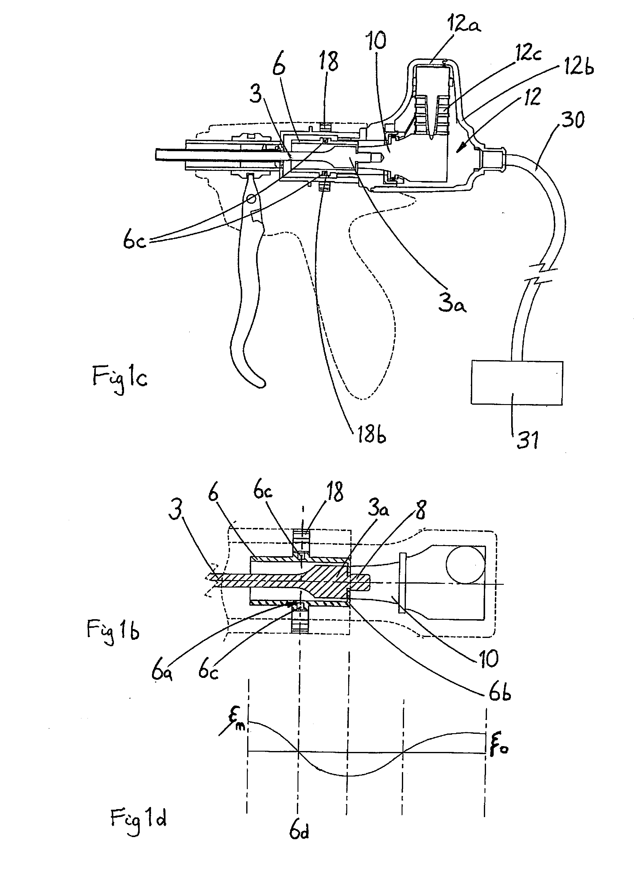
[0096]An alternative means of rotation of the cutting plane of the tool may be effected by the second embodiment illustrated in FIGS. 3a and 3b. The aforementioned isolating sleeve 6, with its same nodal plane 6d, is provided with a raised circumferential flange having a profile comprising a gear ring 6g. A tangentially-mounted electric motor 11, fixed to handpiece casing 1 has a gearbox 11b operatively connected thereto, provided with an output worm gear 11a, which is operatively engaged with said gear ring 6g. The motor 11 is activated by switches 26a and 26b on the exterior of the handpiece casing 1 and conveniently positioned for digital access.
[0097]In the tools illustrated, which contain ‘L-shaped’ transducers 12 adapted to produce torsional mode ultrasonic vibrations, rotation of the cutting plane would be limited to ±90° about a neutral plane. If an alternative axisymmetric transducer 12 were used, both the above approach and that described in the context of FIGS. 1a to 1c w...
third embodiment
[0098]an arrangement for rotating the cutting plane is shown in FIGS. 4a and 4b. The acoustic isolating sleeve 6 is provided with a helically-extending slot 6h, within which is held a hardened ball 6k (see FIG. 4a). The ball 6k is compelled to move in a direction parallel to the longitudinal axis of the waveguide 3 by slideable knob 9b, which is constrained to travel within a longitudinal slot 9a in an outer sleeve 9. Slideable knob 9b is provided with a protruding socket 9c, which receives part of the ball 6k and which also passes through a longitudinal slot 7c in an inner slide sleeve 7. Longitudinal movement of the knob 9b, in the direction of arrows E and E1, thus causes a corresponding rotational displacement of said acoustic isolator 6, and hence the transducer 12 and waveguide 3 connected thereto, as indicated by arrows D and D1. The inner slide sleeve 7 is operatively connected at its distal end to tube holder 14, and at its proximal end to the transducer casing 12a, in orde...
PUM
 Abstract
Description
Claims
Application Information
 - R&D
- Intellectual Property
- Life Sciences
- Materials
- Tech Scout
- Unparalleled Data Quality
- Higher Quality Content
- 60% Fewer Hallucinations
Browse by: Latest US Patents, China's latest patents, Technical Efficacy Thesaurus, Application Domain, Technology Topic, Popular Technical Reports.
© 2025 PatSnap. All rights reserved.Legal|Privacy policy|Modern Slavery Act Transparency Statement|Sitemap|About US| Contact US: help@patsnap.com


