
Apparatus and method for reactive power control

Active Publication Date: 2016-07-21
ENPHASE ENERGY
View PDF11 Cites 9 Cited by
  • Summary
  • Abstract
  • Description
  • Claims
  • Application Information

AI Technical Summary

Benefits of technology

The present invention is a method and device for controlling reactive power. The technical effects of this invention include improved stability, reliability, and efficiency of power systems. It can also reduce downtime for maintenance and improve overall performance of power devices.

Problems solved by technology

Power consumers coupled to the power grid can cause reactive power to be present on the power grid.
Power converters used in alternative energy systems have not been designed to facilitate reactive power control; these power converters are designed for power factor control to ensure the energy that they are producing has a power factor of unity.
As alternative energy systems become larger and larger, in some areas, the power they generate by alternative generator sources may dominate the power on the power grid without any reactive power control.

Method used


Image

  • Apparatus and method for reactive power control
  • Apparatus and method for reactive power control
  • Apparatus and method for reactive power control

Examples


Embodiment Construction

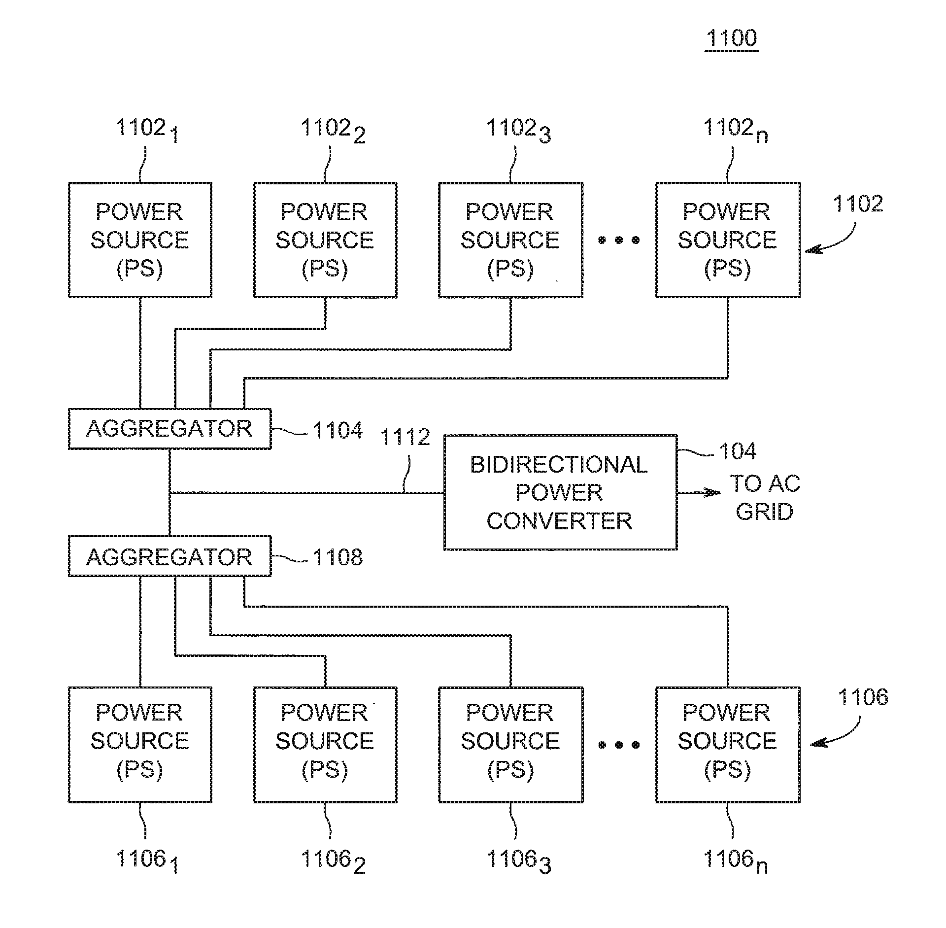
[0028]Embodiments of the present invention include a power converter having reactive power control. More specifically, embodiments of the invention include a bidirectional power converter having the capability of flowing power into and out of a storage element within the power converter. The power converter comprises a DC-side bridge coupled via a resonant tank and transformer to a switch mode cycloconverter coupled to a controller. The controller is adapted to receive a power utility defined reactive power control schedule that is implemented by the power converter. As such, the bidirectional power converter may create reactive power at times and with a magnitude defined in this schedule.

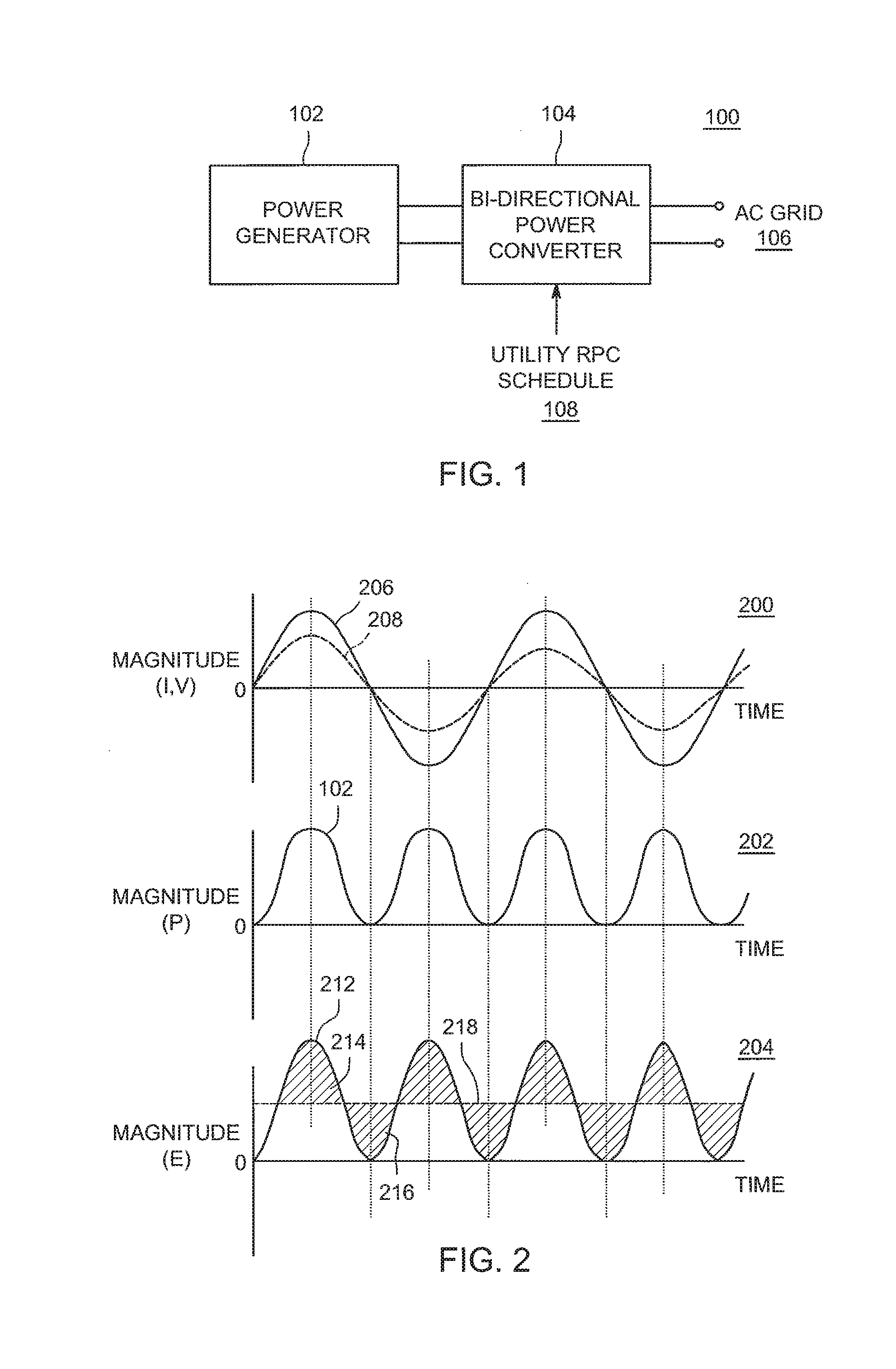
[0029]FIG. 1 is a block diagram of a power generation system 100 in accordance with embodiments of the present invention. The power generation system 100 comprises a power generator 102 coupled to a bidirectional power converter 104. The power generator 102 (or power source) may be any form of DC p...


PUM


Abstract

Apparatus and method for controlling reactive power. In one embodiment, the apparatus comprises a bidirectional power converter comprising a switched mode cycloconverter for generating AC power having a desired amount of a reactive power component.

Description

CROSS-REFERENCE TO RELATED APPLICATIONS[0001]This application claims benefit of U.S. provisional patent application Ser. No. 62 / 105,886, entitled “Power Converter Having Reactive Power Control” and filed Jan. 21, 2015, which is herein incorporated in its entirety by reference.BACKGROUND OF THE INVENTION[0002]1. Field of the Invention[0003]Embodiments of the present invention generally relate to power conversion and, more popularly, to a power converter having reactive power control.[0004]2. Description of the Related Art[0005]Alternative power systems such as solar, wind, and the like generally produce DC power that is converted to AC power for injection onto the AC power grid. Conversion from DC power to AC power must be performed very efficiently to enable these alternative power systems to be commercially viable. One form of highly efficient power converter uses a cycloconverter. A cycloconverter converts a constant voltage, constant frequency AC waveform to another AC waveform o...

Claims


Application Information

Patent Timeline
IPC IPC(8): H02M1/42H02M7/68
CPCH02M7/68H02M1/42H02J3/1835Y02E40/30Y02B70/10
Inventor HARRISON, MICHAEL J.
Owner ENPHASE ENERGY
Learn More