Eureka AIR delivers breakthrough ideas for toughest innovation challenges, trusted by R&D personnel around the world.

A Cleaning Assembly for a Harvester

a cleaning assembly and harvester technology, applied in the field of harvester cleaning assembly, can solve problems affecting the efficiency of the fan system, and achieve the effect of operating the most efficiently

Active Publication Date: 2016-07-14
CNH BELGIUM +1
View PDF7 Cites 12 Cited by
  • Summary
  • Abstract
  • Description
  • Claims
  • Application Information

AI Technical Summary

Benefits of technology

The cleaning assembly described in this patent allows for more flexible and efficient cleaning control during the harvesting process. It uses multiple sub-assemblies that can be separately controlled based on the specific harvesting conditions, without compromising the overall cleaning operation. This means that the composition of the mixture and amount of crop material can vary locally on different areas of the cleaning system, and the cleaning assembly can adapt its operation accordingly to ensure the optimal cleaning operation can be performed to the specific operating circumstances in each region. The cleaning assembly also includes dedicated fans and sieve assemblies for each sub-assembly, which further enhances efficiency. Additionally, the second cleaning sub-assembly can operate most efficiently by operating it in the whirl-layer-phase, resulting in minimal grain losses at the downstream end of this sub-assembly.

Problems solved by technology

However these baffles affect the efficiency of the fan system as they form an obstruction to the airflow generated by the fan.
Furthermore these baffles only allow for a limited modification to the distribution of the airflow along the longitudinal direction of the sieves as in such a setup the airflow will generally always decrease towards the downstream end of the sieves.

Method used


Image

  • A Cleaning Assembly for a Harvester
  • A Cleaning Assembly for a Harvester
  • A Cleaning Assembly for a Harvester

Examples


Embodiment Construction

)

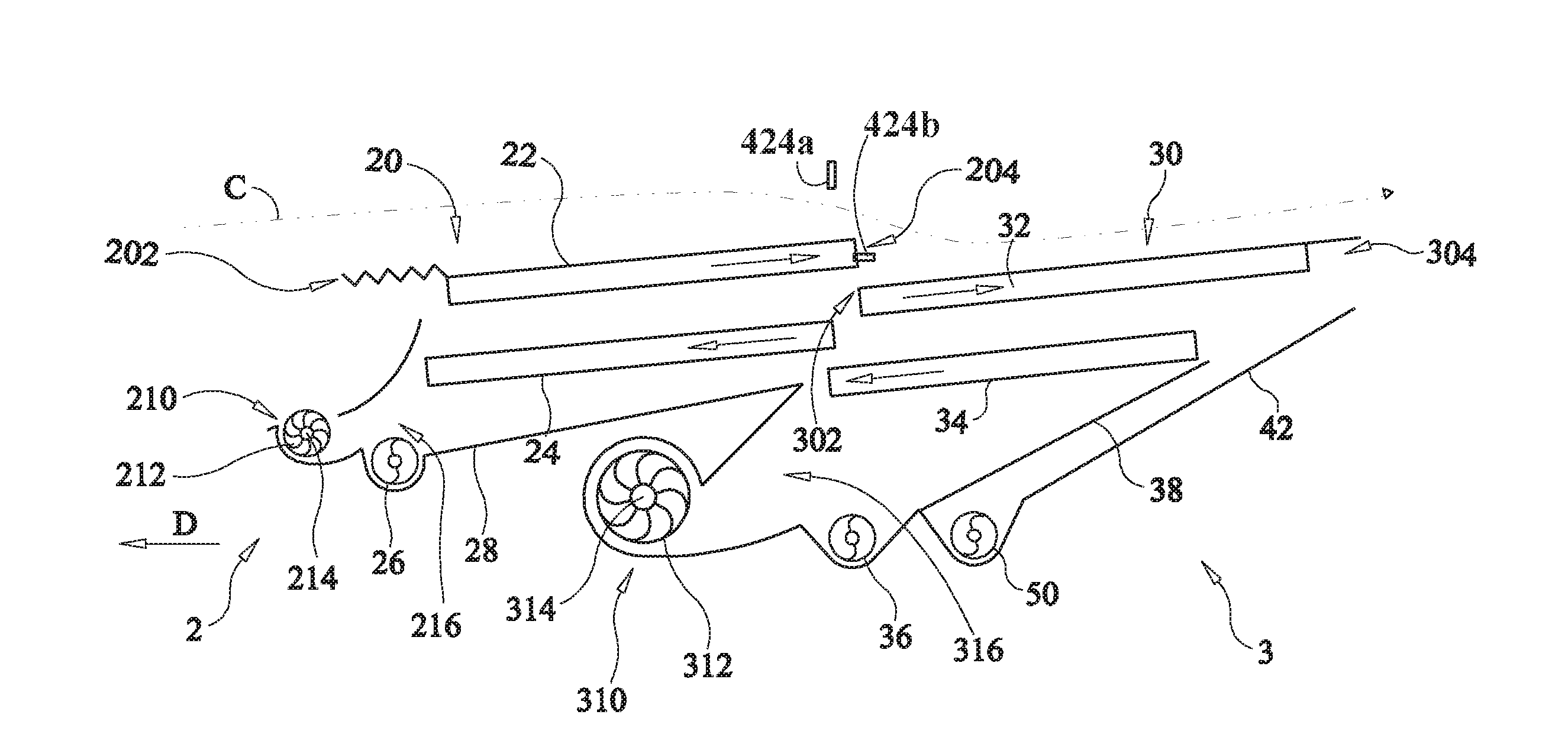
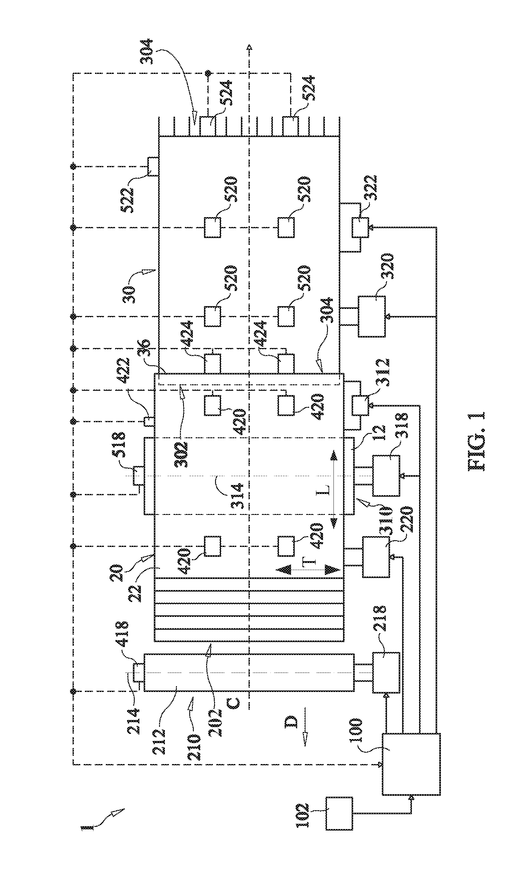
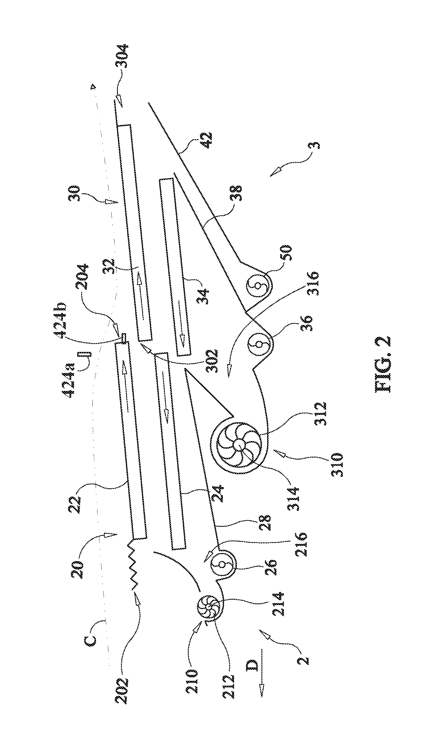
[0080]An embodiment of the cleaning assembly 1 for a harvester according to the invention is schematically shown in FIGS. 1 and 2. The cleaning assembly 1 in use, when part of a harvester, for example a combine harvester or any other suitable harvester, performs the cleaning operation during a harvesting operation of the harvester. During such a harvesting operation the harvester generally travels along a driving direction D on field comprising the crop that needs to be harvested. The harvester processes the harvested crop generally along a direction of the crop flow that, as shown is for example a direction opposite to the direction of travel of the harvester. This means that, for example, crop cut by a header of a combine harvester is moved by a feeder to a threshing and / or separation unit where the grain is removed from the stalk and subsequently moved to and processed by the cleaning assembly 1 along the direction of the crop flow C opposing the driving direction D. The cleanin...


PUM


Abstract

A cleaning assembly for a harvester operable to clean a crop while moving along a direction of the crop flow and comprising multiple cleaning sub-assemblies has a control system coupled to each of the cleaning sub-assemblies and operable to control the operation of each of the cleaning sub-assemblies in function of separate cleaning sub-assembly control settings for each of the cleaning sub-assemblies.

Description

[0001]This application is the US National Stage filing of International Application Serial No. PCT / EP2014 / 068019 filed on Aug. 26, 2014 which claims priority to Belgian Application BE2013 / 0557 filed Aug. 27, 2013, each of which is incorporated herein by reference in its entirety.FIELD OF THE INVENTION[0002]The present invention generally relates to a cleaning assembly for a harvester. More specifically a harvester, such as a combine harvester, comprising a cleaning assembly with reciprocating sieves.BACKGROUND OF THE INVENTION[0003]Such a cleaning assembly generally is arranged in the combine harvester below a threshing and / or separation unit for receiving crop material that is to be subjected to a cleaning operation, such as for example threshed grain from which chaff and other impurities need to be removed in order to retain cleaned grain. The cleaning assembly normally comprises a fan for generating a flow of air that cooperates with a sieve assembly comprising reciprocating siev...

Claims


Application Information

Patent Timeline
IPC IPC(8): A01D41/127A01F12/46A01F12/44
CPCA01D41/1276A01F12/444A01D41/1273A01F12/46A01F12/448A01F12/446
Inventor DUQUESNE, FRANK R.G.MISSOTTEN, BART M.A.SOMERS, TOM N.N.
Owner CNH BELGIUM
Why Eureka
Eureka Blog
Learn More