Method and apparatus for generating a composite image based on an ambient occlusion

a composite image and ambient occlusion technology, applied in the field of map rendering, can solve the problems of combining a standard two-dimensional map or aerial image with a high-definition (hd) three-dimensional content map that may produce less than desirable, dimensional image may contain too much detail, and the transition between the two-dimensional image and the three-dimensional content may be abrup

Active Publication Date: 2016-06-23
HERE GLOBAL BV
View PDF6 Cites 4 Cited by
  • Summary
  • Abstract
  • Description
  • Claims
  • Application Information

AI Technical Summary

Problems solved by technology

Typical methods of combining a standard two dimensional map or aerial image with a high definition (HD) three dimensional content map may produce less than desirable results.
This misalignment may cause the transitions between the two dimensional image and the three dimensional content to be abrupt, detracting from the rendered map.
Further, in some instances the two dimensional image may contain too much detail, which may detract from the three dimensional content of the rendered map.

Method used


Image

  • Method and apparatus for generating a composite image based on an ambient occlusion
  • Method and apparatus for generating a composite image based on an ambient occlusion
  • Method and apparatus for generating a composite image based on an ambient occlusion

Examples


example darkness

of Embossing Ambient Transfer Maps

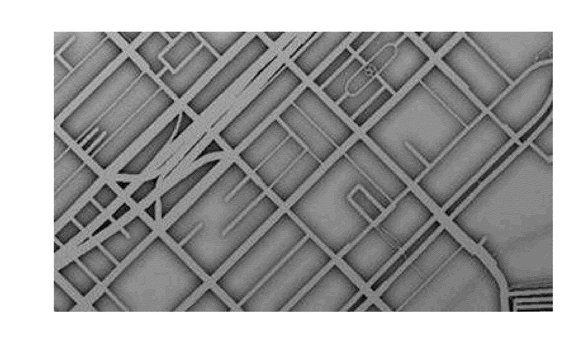
[0073]FIGS. 14A-14E illustrate various darkness levels of the embossing in an composite image. FIG. 14A depicts the two dimensional image, e.g. aerial image. FIGS. 14B-14E depict various darkness levels of the embossing map from a lighter embossing at FIG. 14B to a darker embossing at FIG. 14E.

Example Transition Between a Two Dimensional Image and an Composite Image

[0074]FIGS. 15A-15B, 16A-16B, and 17A-17B illustrate example transitions between two dimensional images and composite images. FIG. 15A depicts a two dimensional image, e.g. aerial image. FIG. 15B depicts a composite image based on the two dimensional image and a embossing map generated based on the ambient occlusions of a three dimensional building model.

[0075]FIG. 16A depicts a two dimensional image, e.g. aerial image. FIG. 16B depicts a composite image based on the two dimensional image and an embossing map generated based on three dimensional LiDAR geometry model. Details of the two di...


PUM


Abstract

A method, apparatus and computer program product are provided for non-occluding overlay of user interface or information elements on a contextual map. A method is provided including receiving a two dimensional image associated with a geographic area or object, receiving geometry model associated with the associated with the geographic area, generating an embossing map based on ambient occlusions associated with the geometry model, and generating a composite image based on the two dimensional image and the embossing map.

Description

TECHNOLOGICAL FIELD[0001]An example embodiment of the present invention relates to map rendering and, more particularly, to generating a composite image based on an ambient occlusion.BACKGROUND[0002]Typical methods of combining a standard two dimensional map or aerial image with a high definition (HD) three dimensional content map may produce less than desirable results. Typically, the three dimensional content is overlaid on the two dimensional images, such as a map or aerial image, which may obscure the two dimensional image. This may be particularly true in an instance in which the context map is a high definition (HD) three dimensional road content map, due to the lane modeling and complex intersections. In these instances the road geometry is larger than the simple centerline road models.[0003]In some examples, the two dimensional image and the three dimensional content may not align, for example the shape of the roads may differ slightly, even in idealized presentations. This ...

Claims


Application Information

Patent Timeline
Patent Type & Authority Applications(United States)
IPC IPC(8): G06T17/05G06T15/50
CPCG06T15/50G06T17/05G01C21/3638G06T11/60G06T2207/10032
Inventor LYNCH, JAMES D.
Owner HERE GLOBAL BV
Why Eureka
Try Eureka