
Connector for Steel Reinforcing Bars

Inactive Publication Date: 2016-06-23
LIN LUNG CHANG
View PDF22 Cites 5 Cited by
  • Summary
  • Abstract
  • Description
  • Claims
  • Application Information

AI Technical Summary

Benefits of technology

The invention is a connector for steel reinforcing bars that is easy to use and can securely connect two separate reinforcing bars together. This makes it more convenient and efficient than existing methods of joining bars.

Problems solved by technology

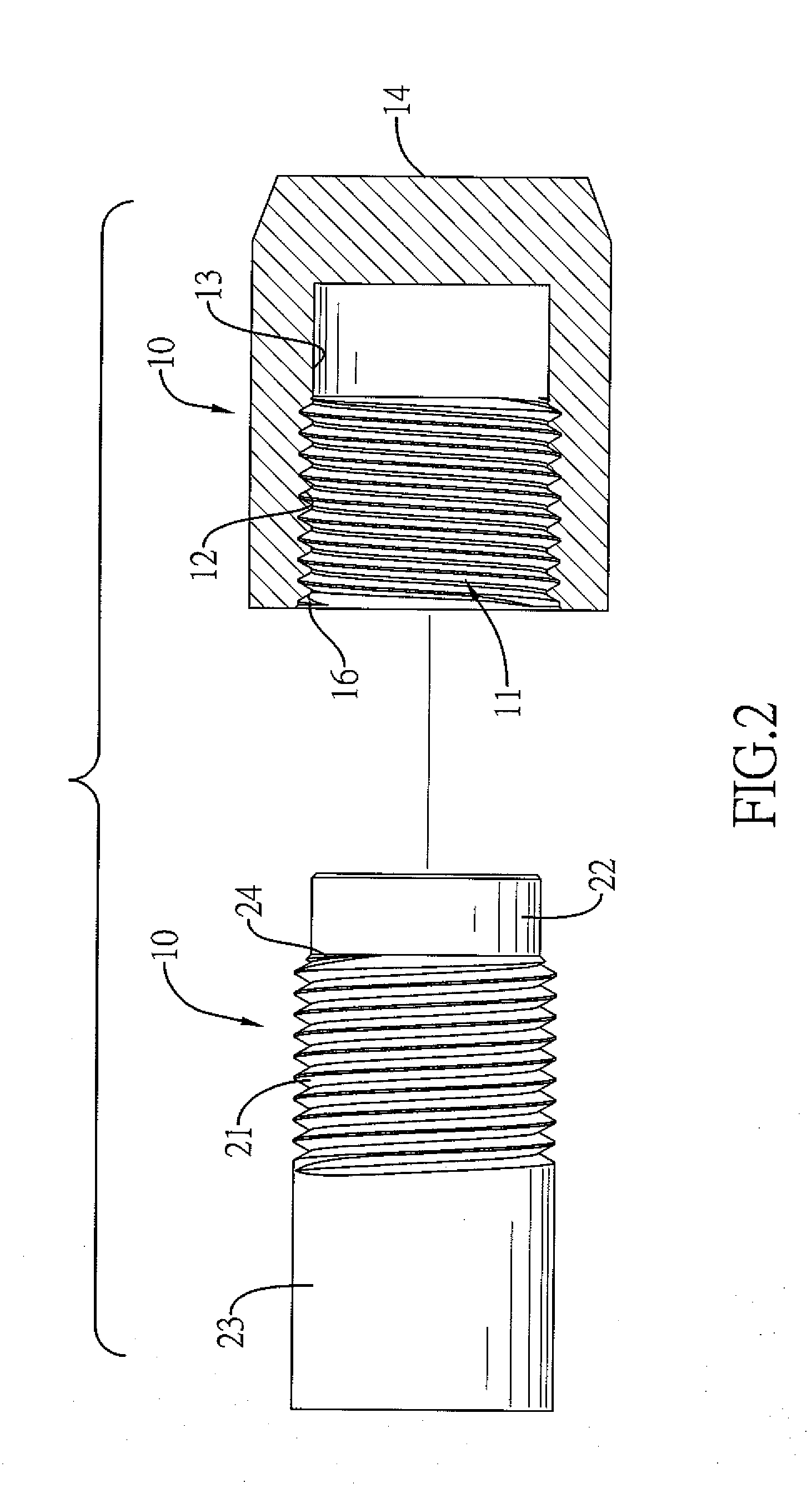
However, the female screw line cannot be formed fully in the threaded hole of the female member to form a straight section in an inner end of the threaded hole.
Due to the conical portion of the screw rod and the straight section of the threaded hole, the screw rod cannot be fully screwed with the threaded hole at the inner end of the threaded hole, and this will shorten an engaging length between the threaded hole and the screw rod and will influence the structural strength between an engagement between the female member and the male member of the conventional connector.

Method used


Image

  • Connector for Steel Reinforcing Bars
  • Connector for Steel Reinforcing Bars
  • Connector for Steel Reinforcing Bars

Examples


first embodiment

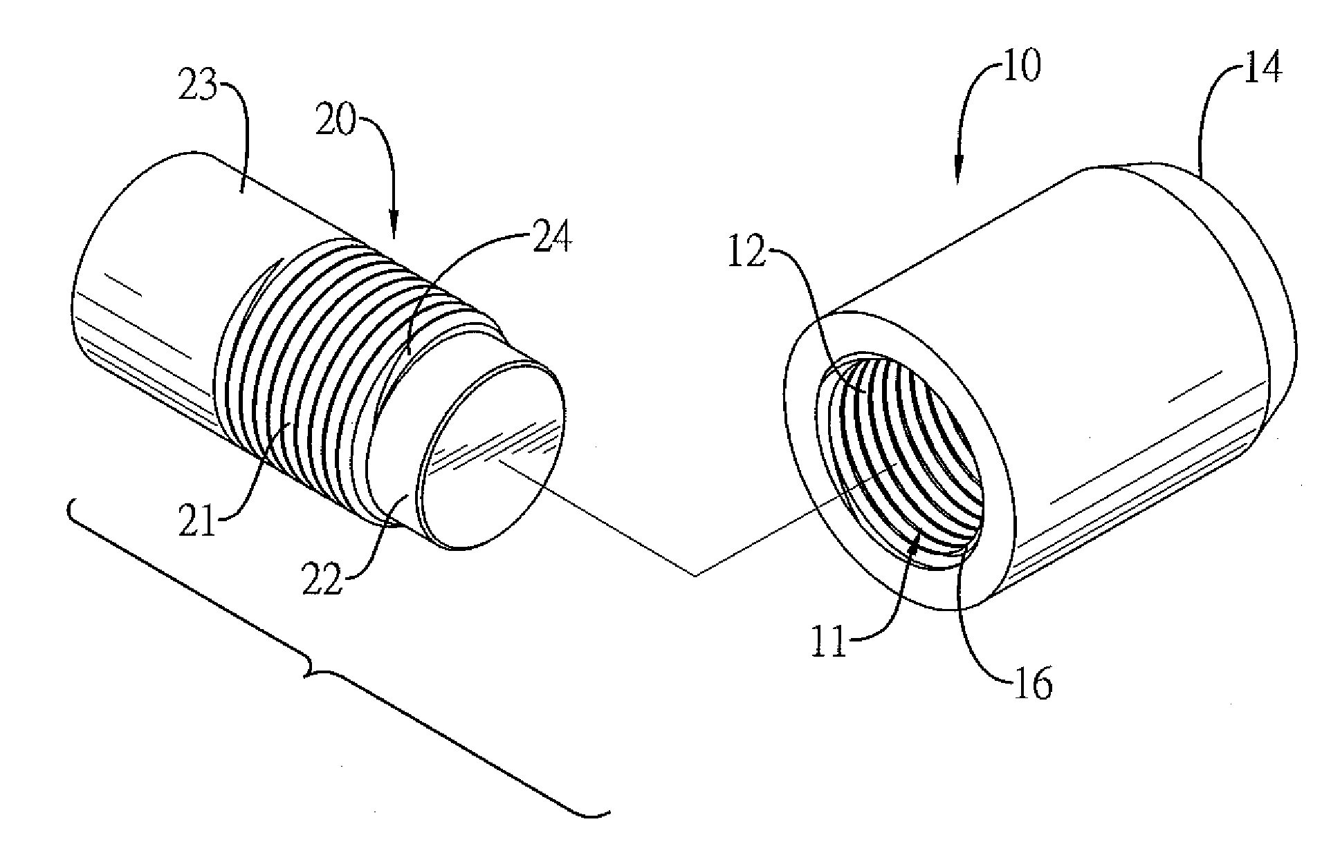
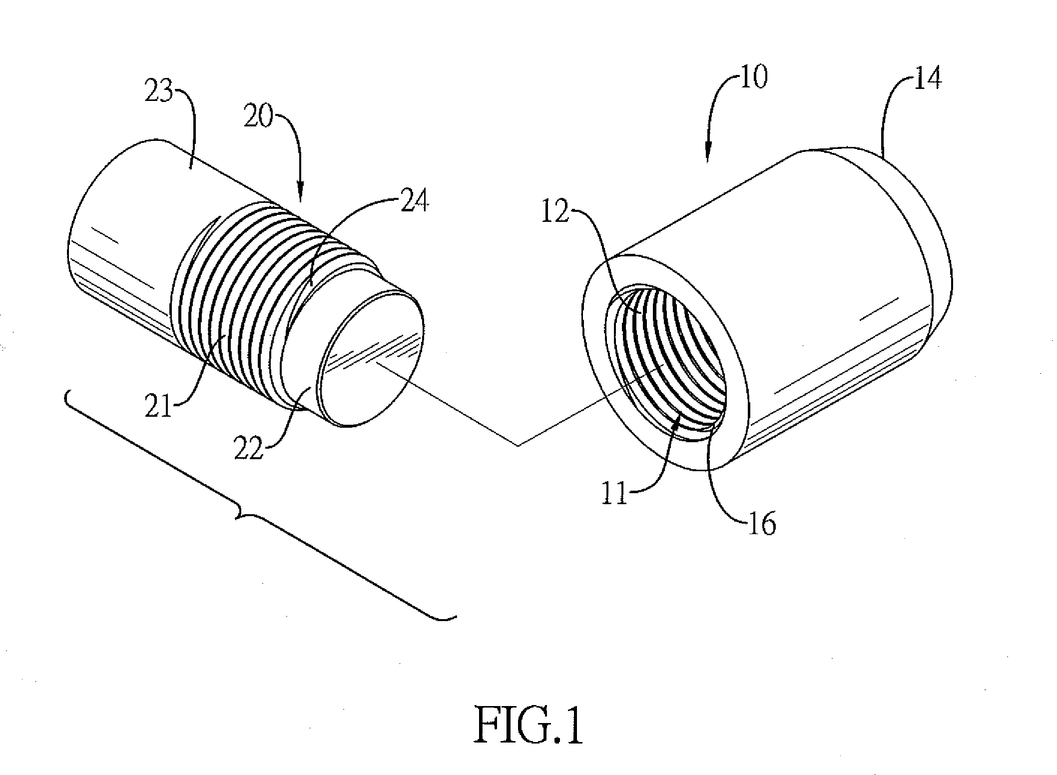
[0020]With reference to FIGS. 1 and 2, a connector for steel reinforcing bars in accordance with the present invention has a female member 10 and a male member 20.

[0021]The female member 10 may be made of steel and has an open side, a closed side 14, and a threaded hole 11. The closed side 14 is opposite to the open side of the female member 10. The threaded hole 11 is formed through the open side of the female member 10 and has a threaded section 12 and a straight section 13. The threaded section 12 is formed in the threaded hole 11 adjacent to the open side of the female member 10 and has multiple female screw lines and an inner diameter. Preferably, the threaded section 12 may have two female screw lines or three female screw lines. With further reference to FIGS. 2 and 3, each one of the multiple screw lines has a thread inlet 16 formed on an end of the threaded section 12.

[0022]The straight section 13 is formed in the threaded hole 11 between the threaded section 12 and the clo...

second embodiment

[0033]With reference to FIG. 8, a connector for steel reinforcing bars in accordance with the present invention has a female member 10A and two male members 20A, 20B.

[0034]The female member 10A may be made of steel and has two sides and a threaded hole 11A. The threaded hole 11A is axially formed through the two sides of the female member 10A, and has two threaded sections 12A, 12B and a straight section 13A. The threaded sections 12A, 12B are formed in the female member 10A respectively adjacent to the two sides of the female member 10A, and each one of the threaded sections 12A, 12B has a screw direction, an inner diameter and multiple female screw lines. The screw directions of the two threaded sections 12A, 12B are opposite. Preferably, each one of the threaded section 12A, 12B may have two female screw lines or three female screw lines. Furthermore, each one of the two threaded sections 12A, 12B has multiple female thread inlets formed in the corresponding threaded section 12A,...


PUM


Abstract

A connector for steel reinforcing bars has a female member and at least one male member. The female member has a threaded hole. The threaded hole is formed in the female member and has at least one threaded section and a straight section. The straight section is formed in the threaded hole, communicates with the at least one threaded section, and has an inner diameter smaller than the inner diameter of the at least one threaded section. The at least one male member is connected to the female member, and each one of the at least one male member has a screw rod section, a cylindrical section, and a connecting section. The screw rod section is formed between the cylindrical section and the connecting section and is screwed with the at least one threaded section. The cylindrical section is corresponding to and mounted in the straight section.

Description

BACKGROUND OF THE INVENTION[0001]1. Field of the Invention[0002]The present invention relates to a connector, and more particularly to a connector for steel reinforcing bars that can be used easily and can connect two separate steel reinforcing bars securely with each other conveniently.[0003]2. Description of Related Art[0004]A conventional connector that is used to connect two separate steel reinforcing bars with each other has a female member and at least one male member. The female member has a threaded hole. Each one of the at least one male member has a screw rod. The female member and the male member are respectively and securely connected to two ends of the separate steel reinforcing bars by welding. Then, the separate steel reinforcing bars can be connected with each other by an engagement between the threaded hole of the female member and the screw rod of the male member. In addition, another conventional connector for steel reinforcing bars has a female member and two mal...

Claims


Application Information

Patent Timeline
IPC IPC(8): F16B7/18
CPCF16B7/182E04C5/165E04C5/16E04C5/162E04C5/18
Inventor LIN, LUNG-CHANG
Owner LIN LUNG CHANG
Learn More