Eureka AIR delivers breakthrough ideas for toughest innovation challenges, trusted by R&D personnel around the world.

Elevator car arrangement and a connection element

a technology of connection element and elevator car, which is applied in the direction of elevators, building lifts, transportation and packaging, etc., can solve the problems of bending moment, causing both lateral vibration and structure-borne noise in the walls of the elevator car, and reducing the service life of the elevator. , to achieve the effect of reducing vibration

Active Publication Date: 2016-06-16
KONE CORP
View PDF12 Cites 0 Cited by
  • Summary
  • Abstract
  • Description
  • Claims
  • Application Information

AI Technical Summary

Benefits of technology

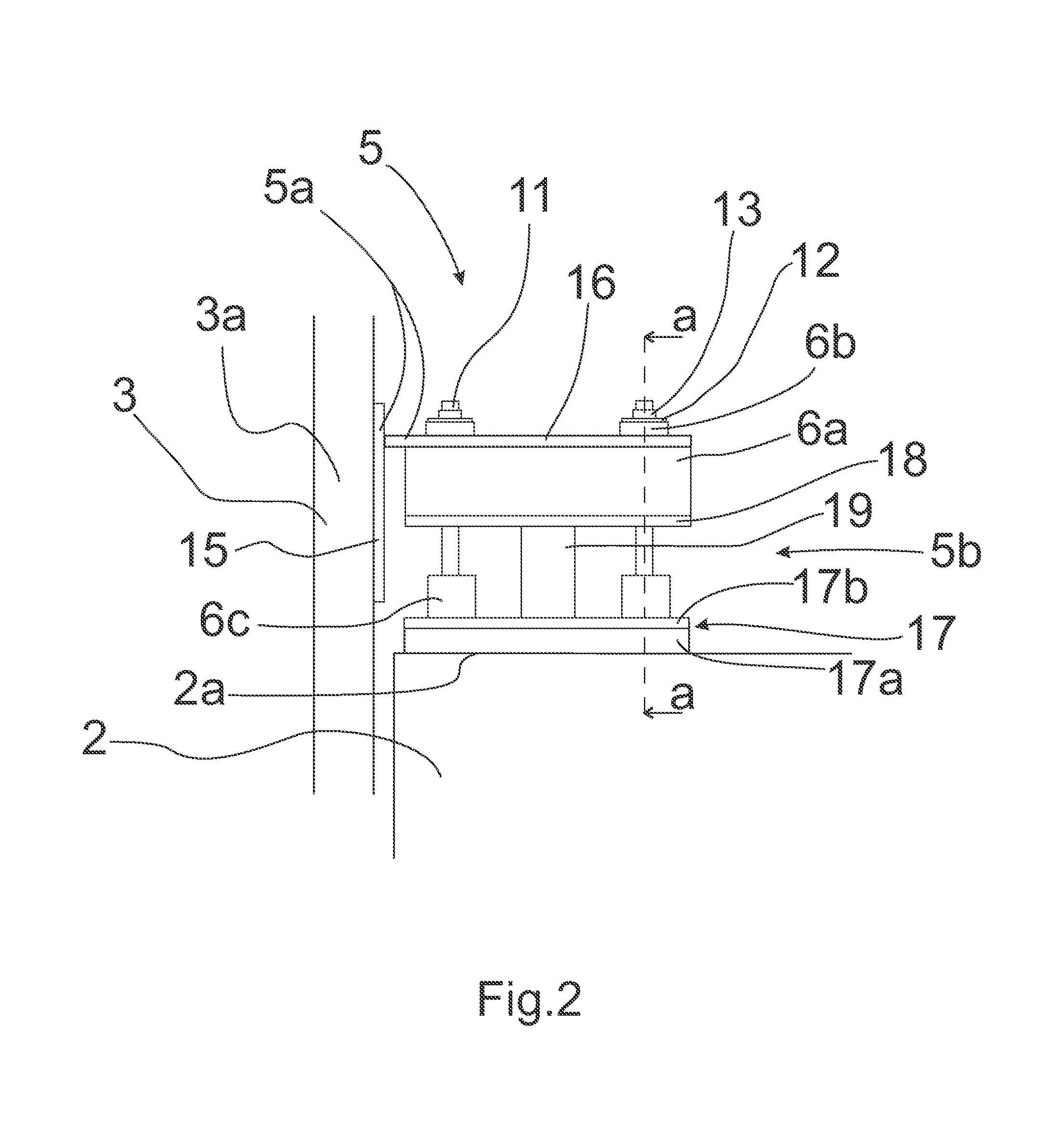
The invention is about reducing vibrations in elevators caused by the joints of guide rails. It achieves this by adding a damper in the connection between the car body and the sling. This connection is between the side support of the sling and the roof of the car body. This arrangement prevents bending moments that could occur between the upper horizontal support and the roof. Another advantage is that the stresses in the damping material are shared, which results in optimal behavior.

Problems solved by technology

These joints and possible impreciseness in guide rail alignment causes vibrations to the elevator car body via the elevator car sling connected to the elevator car body.
This means that ride comfort in the elevator suffers and noise increases, which is especially the case with high speed elevators.
Problem with the prior art is that lateral vibrations caused by guide rails are formed in the upper beam of the sling and although they may be somehow dampened the upper beam may also cause some bending moment which during time will affect to the damping especially in the high speed elevators.
Another problem is that in case of high rise elevators the vibrations of the top side of the elevator car become more relevant for a large range of frequency and if they are not isolated they may induce both lateral vibrations and structure borne noise in the walls of the elevator car.

Method used


Image

  • Elevator car arrangement and a connection element
  • Elevator car arrangement and a connection element
  • Elevator car arrangement and a connection element

Examples


Embodiment Construction

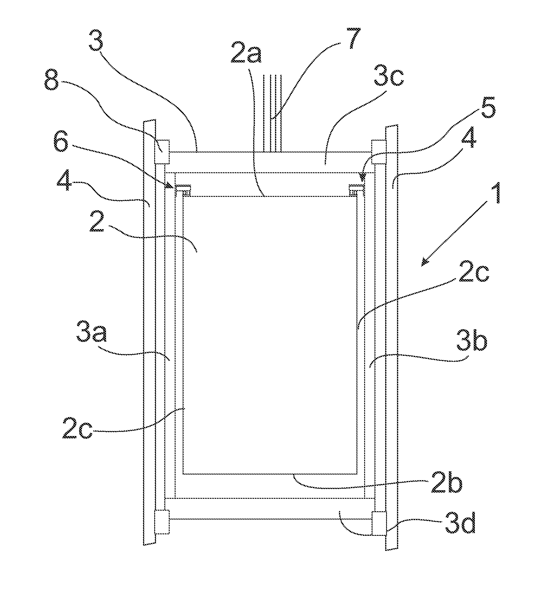
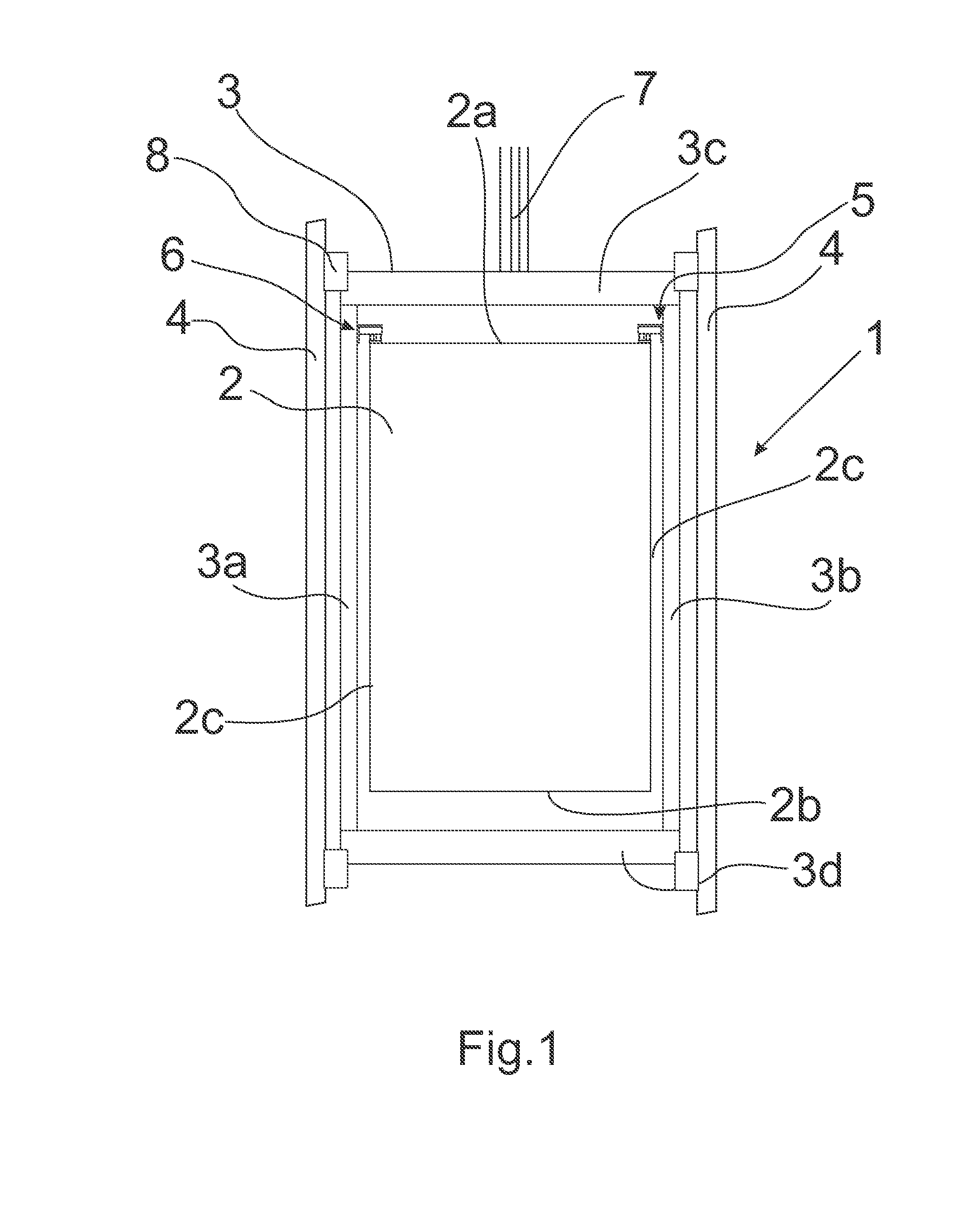
[0015]FIG. 1 shows the elevator car arrangement 1 according to the invention. The elevator car arrangement 1 comprises an elevator car body 2 comprising a roof 2a, a bottom 2b and side walls 2c, and an elevator car sling 3 for being guided along vertically extending guide rails 4. The elevator car sling 3 comprises at least a first vertical side support 3a, a second vertical side support 3b and an upper horizontal support 3c, which said supports 3a, 3b, 3c are connected to each other to form the sling 3. The elevator car body 2 is connected to the elevator car sling 3 such that the elevator car body 2 is supported in the elevator car sling 3. This means that the elevator car sling 3 forms an outer periphery of the elevator car arrangement 1. The elevator car sling may also comprise a lower horizontal support 3d but this is not necessary in all elevator car arrangements 1. In the case that the elevator car sling 3 comprises four supports 3a, 3b, 3c, 3d they form a closed ring inside ...


PUM


Abstract

An elevator car arrangement includes an elevator car body including a roof, a bottom and side walls, and an elevator car sling for being guided along vertically extending guide rails. The elevator car sling includes at least a first vertical side support, a second vertical side support and an upper horizontal support, which supports are connected to each other to form the sling. The elevator car body is connected to the elevator car sling such that the elevator car body is supported in the elevator car sling. The elevator car arrangement further includes a connection element for connecting the elevator car body to the elevator car sling such that the connection element is arranged between the roof of the elevator car body and the vertical side support of the elevator car sling, the connection element including a damper for damping vibrations caused by guide rails. A connection element for connecting an elevator car body to an elevator car sling is provided to form the elevator car arrangement.

Description

FIELD OF THE INVENTION[0001]The invention relates to an isolation of an elevator car, in particular to an arrangement for isolating elevator car from vibrations coming from guide rails for improving ride comfort of an elevator.BACKGROUND OF THE INVENTION[0002]Usually in elevators the elevator car is generally fitted inside an elevator car sling, which the elevator car sling is suspended by hoisting roping and fitted to travel along guide rails. The guide rails are formed by connecting successive guide rail members together such that joints are formed in the assembled guide rails. These joints and possible impreciseness in guide rail alignment causes vibrations to the elevator car body via the elevator car sling connected to the elevator car body. This means that ride comfort in the elevator suffers and noise increases, which is especially the case with high speed elevators. Ride comfort for high speed elevators is very much influenced by the interface between the elevator car and th...

Claims


Application Information

Patent Timeline
Patent Type & Authority Applications(United States)
IPC IPC(8): B66B11/02
CPCB66B11/0226B66B11/0273
Inventor ROIVAINEN, GABRIELAVESTERINEN, MIKKO
Owner KONE CORP
Why Eureka
Eureka Blog
Learn More