Mountable wing tip device for mounting on a rotor blade of a wind turbine arrangement

Active Publication Date: 2016-06-02
YOUWINENERGY
View PDF6 Cites 1 Cited by
  • Summary
  • Abstract
  • Description
  • Claims
  • Application Information

AI Technical Summary

Benefits of technology

The present invention provides a rotor blade with a wing tip device that reduces drag and bending moments, while also preventing aerodynamic short-circuit and providing a laminar flow of wind across the blade. The wing tip device is easy to install and can be separately transported to the construction site, minimizing damage and reducing costs. The wing tip device is designed in a triangular shape with a leading edge region that has a V-shape or an arced tip portion to enhance aerodynamic performance.

Problems solved by technology

One of the losses which are present in the blade tip region occurs primarily due to the axial direction which the airflow assumes as it flows over the rotor blade.
Due to such non-regular airflow along the blade tip region, aerodynamic losses are introduced which in turn reduce the lift-to-drag efficiency of the rotor blade.
However, despite the curved tip of the rotor blades, an aerodynamic short-circuit between a pressure side and a suction side of the rotor blade might occur.
Such designs however do not address the losses that occur due to the formation of the vortices.
In cases where the blade tip is part of the rotor blades, it is very likely that the blade tips may get damaged during transportation.
Also, if the blade tips suffer damage in the course of their operation, or due to natural occurrences such as lightening, the entire rotor blade has to be replaced.
This further is likely to increase the operational costs associated with the wind turbine.
In addition, it may be inconvenient and time-consuming to perform any checks on the blade tips, once the wind turbine is operational.
Further, since the blade tips typically extend either towards the suction side or the pressure side of the rotor blade, this may cause imbalance when the wind turbine is in operation, thereby causing vibrations in the wind turbine.
Such a fast installation saves costs and allows replacing the wing tip device after damage.

Method used


Image

  • Mountable wing tip device for mounting on a rotor blade of a wind turbine arrangement
  • Mountable wing tip device for mounting on a rotor blade of a wind turbine arrangement
  • Mountable wing tip device for mounting on a rotor blade of a wind turbine arrangement

Examples


embodiment

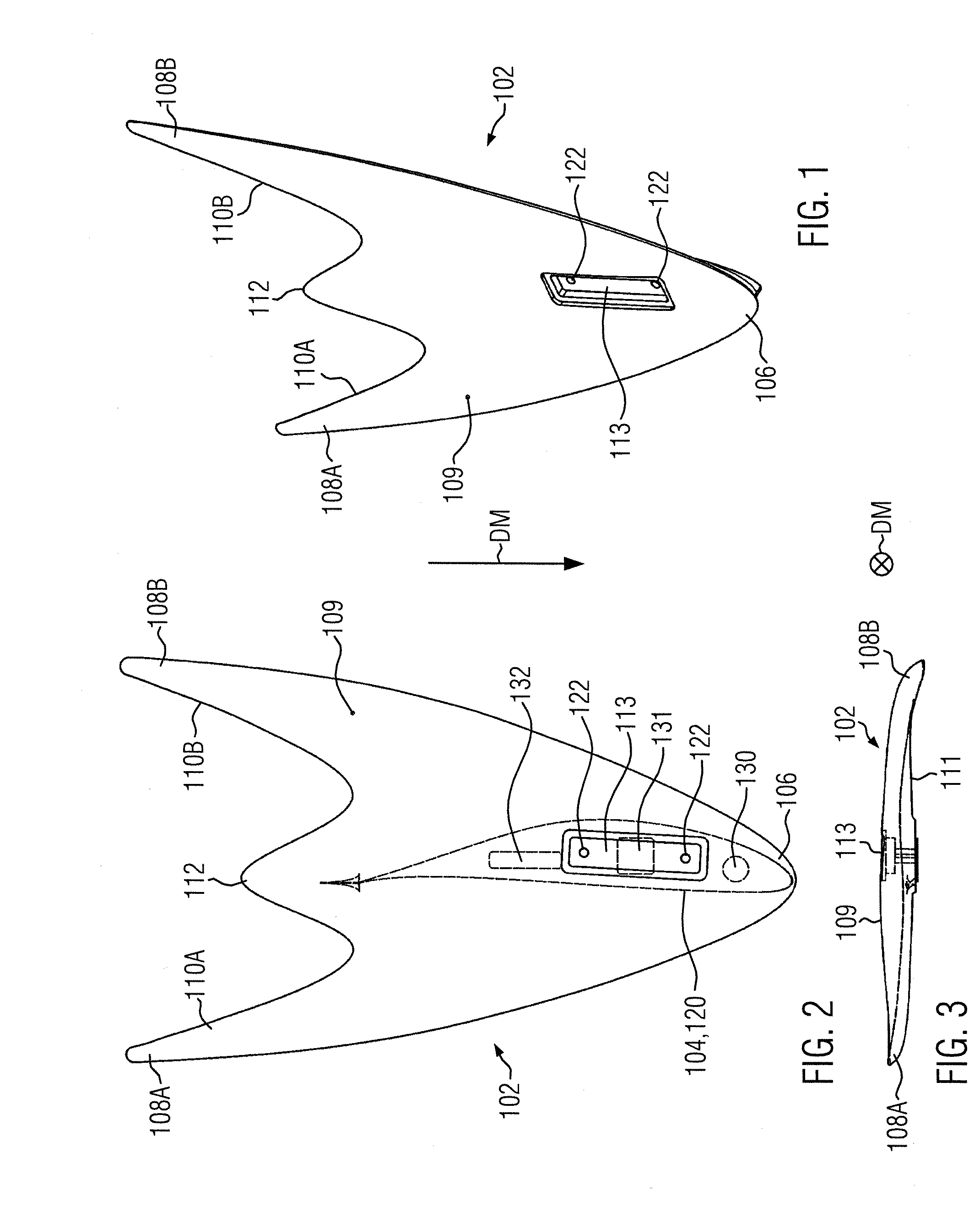
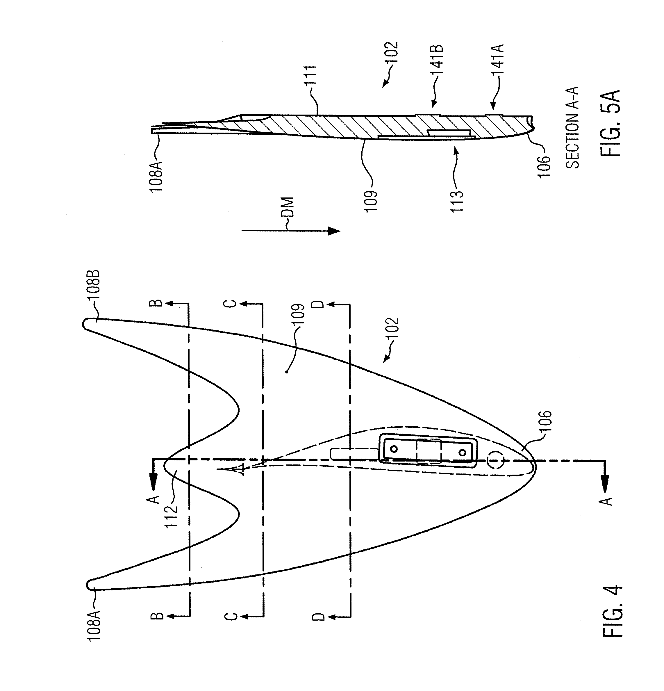
[0057]An embodiment of a mountable wing tip device 102 of the present subject matter is shown in FIGS. 1 and 2 in a three-dimensional view and a top-view, respectively.

[0058]The wing tip device 102 comprises a forward extremity 106 and three rearward extremities 108A, 108B and 112. The forward extremity 106 and the rearward extremities 108A and 108B are triangularly arranged. Between the two rearward extremities, in particular in the middle of the rearward extremities 108A and 108B, the rearward extremity 112 is positioned.

[0059]The forward extremity 106 and the rearward extremities 108A and 108B are arranged in a triangle which means that the distance between the forward extremity 106 and the rearward extremities 108A, B is similar. However, the distance between the rearward extremity 112 and the forward extremity 106 comprises a shorter length than the distance between the forward extremity and the two other rearward extremities 108A, B.

[0060]The mountable wing tip device 102 also...


PUM


Abstract

A mountable wing tip device (102) for mounting on a rotor blade of a wind turbine is disclosed which comprises a forward extremity (106) and at least two rearward extremities (108A, 108B, 112), wherein the forward extremity (106) and the at least two rearward extremities (108A, 108B, 112) are triangularly arranged, a leading edge region extending between the forward extremity (106) and the at least two rearward extremities (108A, 108B, 112), and a trailing edge region extending between the rearward extremities (108A, 108B, 112), a root region (113) at which the wing tip device (102) is mountable on an end of the rotor blade, wherein the root region (113) is positioned between the leading edge region and the trailing edge region.

Description

BACKGROUND OF THE DESCRIPTION[0001]The present subject matter relates to a mountable wing tip device, a blade tip assembly and a wind turbine arrangement.[0002]In a commonly known wind turbine assembly, a rotor blade of a rotor component converts wind energy to low speed rotational energy. Such a rotor blade is connected to a generator positioned in a hub of the wind turbine assembly, wherein the hub is arranged in order to drive the generator while the rotor blade converts wind energy. Opposite to the end of the rotor blade arranged at the hub, the rotor blade comprises a free end which oscillates due to the mixture of the air flow from the pressure and suction side of the rotor blade.[0003]Typically, a rotor blade is designed to be broader near a root portion and narrower towards a tip portion of the rotor blade wherein the tip portion comprises the free end of the rotor blade. As also known, for some of the prevalent rotor blade designs, the blade tip region is characterized by t...

Claims


Application Information

Patent Timeline
IPC IPC(8): F03D1/06F03D9/00
CPCF03D9/002F03D1/0633F03D1/0641F05B2240/302F05B2250/11F03D9/25F05B2240/307Y02E10/72F03D1/0658F03D1/0675F05B2240/30
Inventor ROHDEN, ROLF
Owner YOUWINENERGY
Why Eureka
Try Eureka