Printing apparatus
a printing apparatus and printing technology, applied in printing, typewriters, power drive mechanisms, etc., can solve the problems of burden on the operator and inability to easily perform printing, and achieve the effect of reducing the burden on the operator and favorable printing
- Summary
- Abstract
- Description
- Claims
- Application Information
AI Technical Summary
Benefits of technology
Problems solved by technology
Method used
Image
Examples
first embodiment
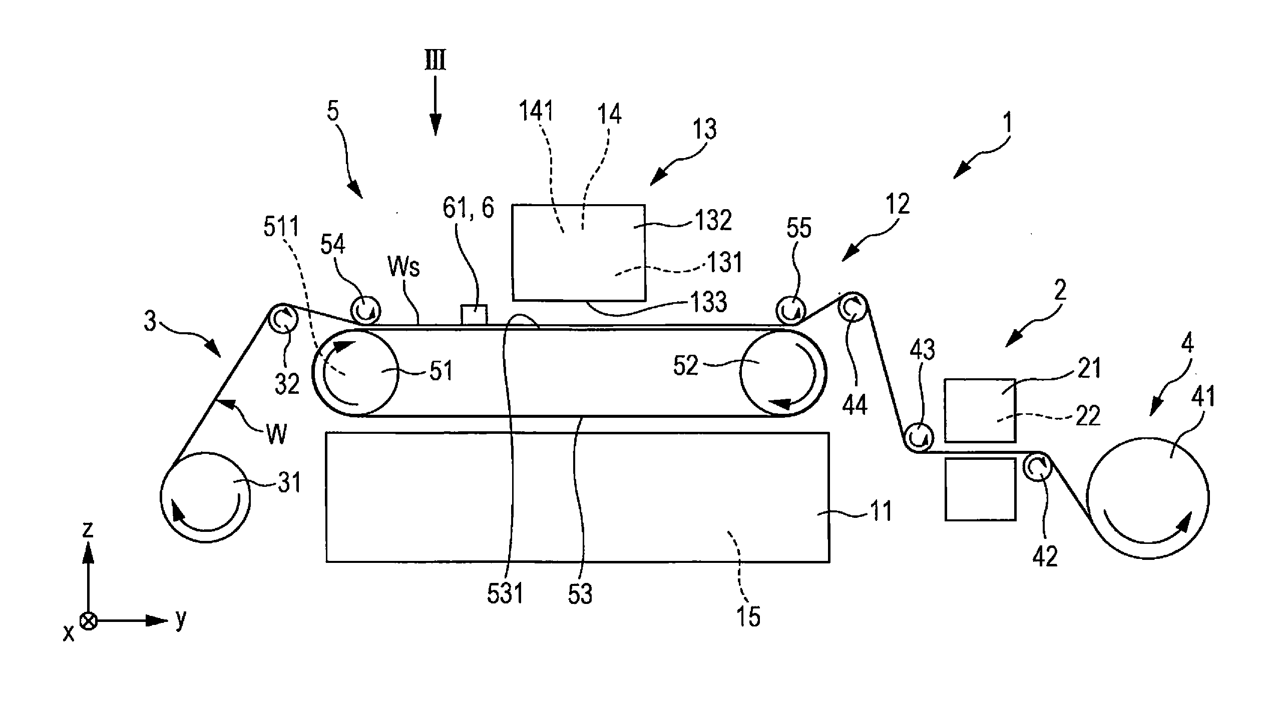
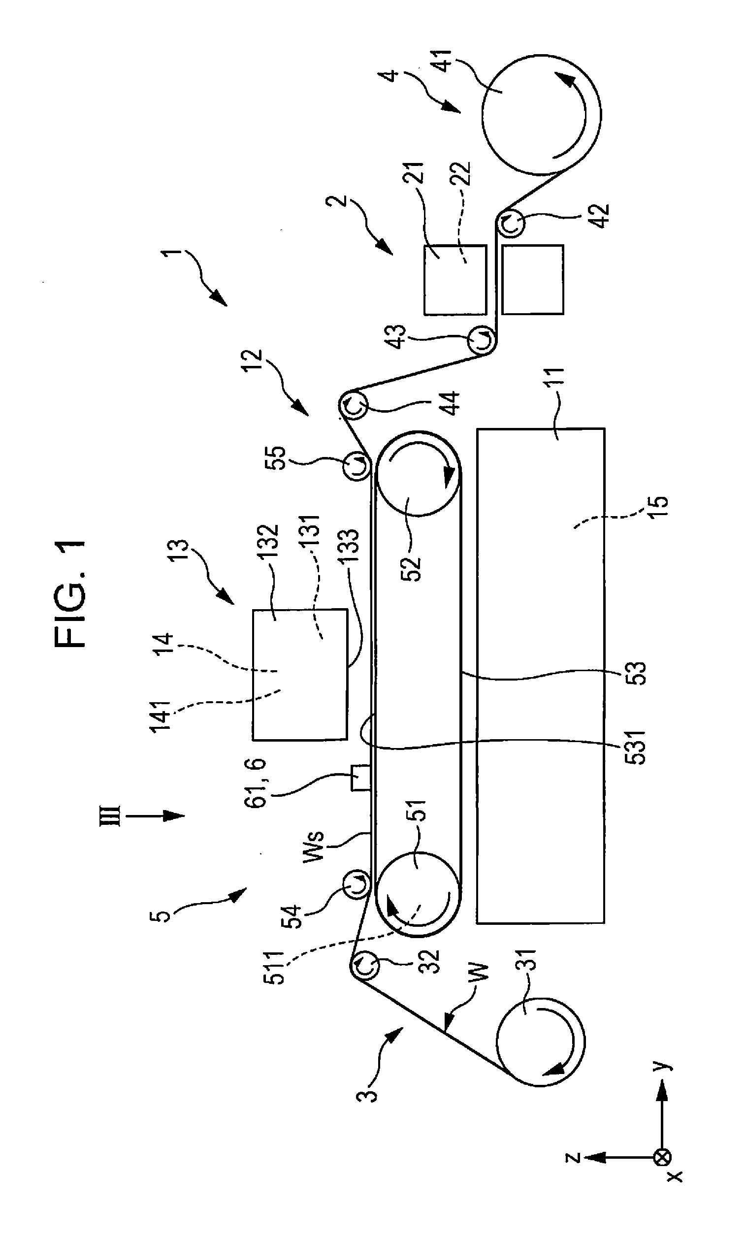
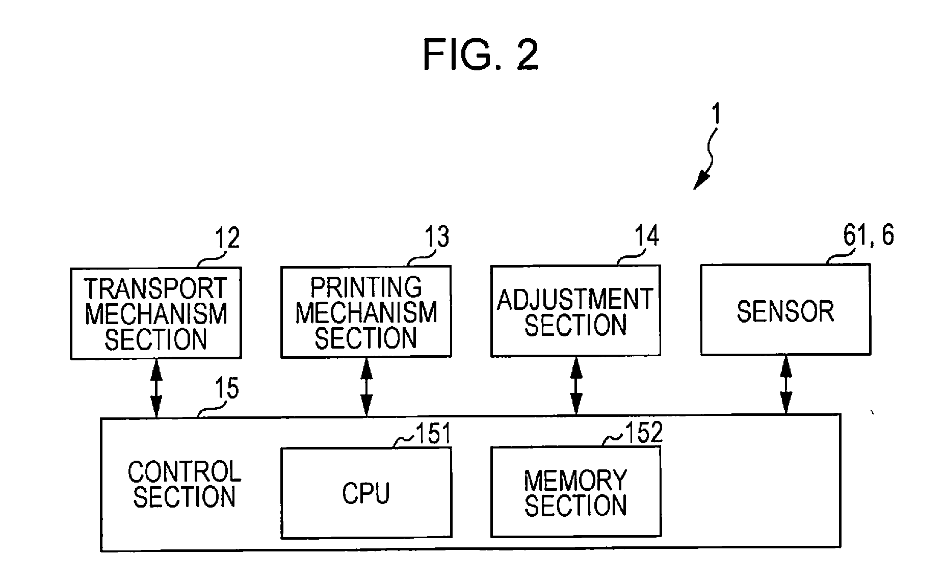
[0066]FIG. 1 is a side surface view schematically illustrating a first embodiment of the printing apparatus of the invention. FIG. 2 is a block diagram of the printing apparatus which is illustrated in FIG. 1. FIG. 3 is a diagram viewed from an arrow III direction in FIG. 1. FIGS. 4 to 18 are diagrams for describing operations of the printing apparatus which is illustrated in FIG. 1. FIG. 19 is a graph illustrating a standard curve of the upper surface position and the amount of received light of the recording medium. FIG. 20 is a graph illustrating a standard curve of the upper surface position and the separation distance of the recording medium. FIG. 21 is a flowchart illustrating a control program of the printing apparatus which is illustrated in FIG. 1. FIG. 22 is a flowchart illustrating a control program of the printing apparatus which is illustrated in FIG. 1.
[0067]Here, for convenience of explanation, in FIG. 1 and FIG. 3 (in the same manner in FIG. 27), an x axis, a y axis,...
second embodiment
[0146]FIGS. 23A to 23G are enlarged side surface diagrams illustrating the printing apparatus of the invention (second embodiment).
[0147]The second embodiment of the printing apparatus of the invention will be described below with reference to the drawings, but will be described focusing on differences from the embodiment described above, and the same matter is omitted from the description.
[0148]The present embodiment is the same as the first embodiment aside from the control program being different.
[0149]As shown in FIGS. 23A to 23G, in the printing apparatus 1, it is easy to understand the distance by which the wrinkle Wx is transported from when the wrinkle Wx is detected for the ink jet head 131 to be raised. This will be described below.
[0150]FIG. 23A is a diagram illustrating a printing apparatus 1A when the wrinkle Wx is considered to be generated. The distance L2 from the front end Wxf of the wrinkle Wx to the ink jet head 131 when the wrinkle Wx is considered to be generate...
third embodiment
[0158]FIGS. 24 to 26 are diagrams illustrating operations of the printing apparatus of the invention (third embodiment). FIG. 27 is a diagram illustrating the printing apparatus of the invention (third embodiment) viewed from the upstream side.
[0159]The third embodiment of the printing apparatus of the invention will be described below with reference to the drawings, but will be described focusing on differences from the embodiments described above, and the same matter is omitted from the description.
[0160]The present embodiment is the same as the first embodiment aside from the control program being different.
[0161]As shown in FIG. 24, in the present embodiment, a printing apparatus 1B adjusts the timing at which the ink 100 is discharged according to the extent of the separation distance G. This will be described below. Here, in the embodiment, the “raised portion” is described as a join Wt.
[0162]FIG. 24, is a diagram in which the join Wt comes close to the ink jet head 131 by mov...
PUM
 Abstract
Description
Claims
Application Information
 - R&D
- Intellectual Property
- Life Sciences
- Materials
- Tech Scout
- Unparalleled Data Quality
- Higher Quality Content
- 60% Fewer Hallucinations
Browse by: Latest US Patents, China's latest patents, Technical Efficacy Thesaurus, Application Domain, Technology Topic, Popular Technical Reports.
© 2025 PatSnap. All rights reserved.Legal|Privacy policy|Modern Slavery Act Transparency Statement|Sitemap|About US| Contact US: help@patsnap.com


