
Multi-device sensor subsystem joint optimization

Active Publication Date: 2016-02-18
QUALCOMM INC
View PDF4 Cites 28 Cited by
  • Summary
  • Abstract
  • Description
  • Claims
  • Application Information

AI Technical Summary

Benefits of technology

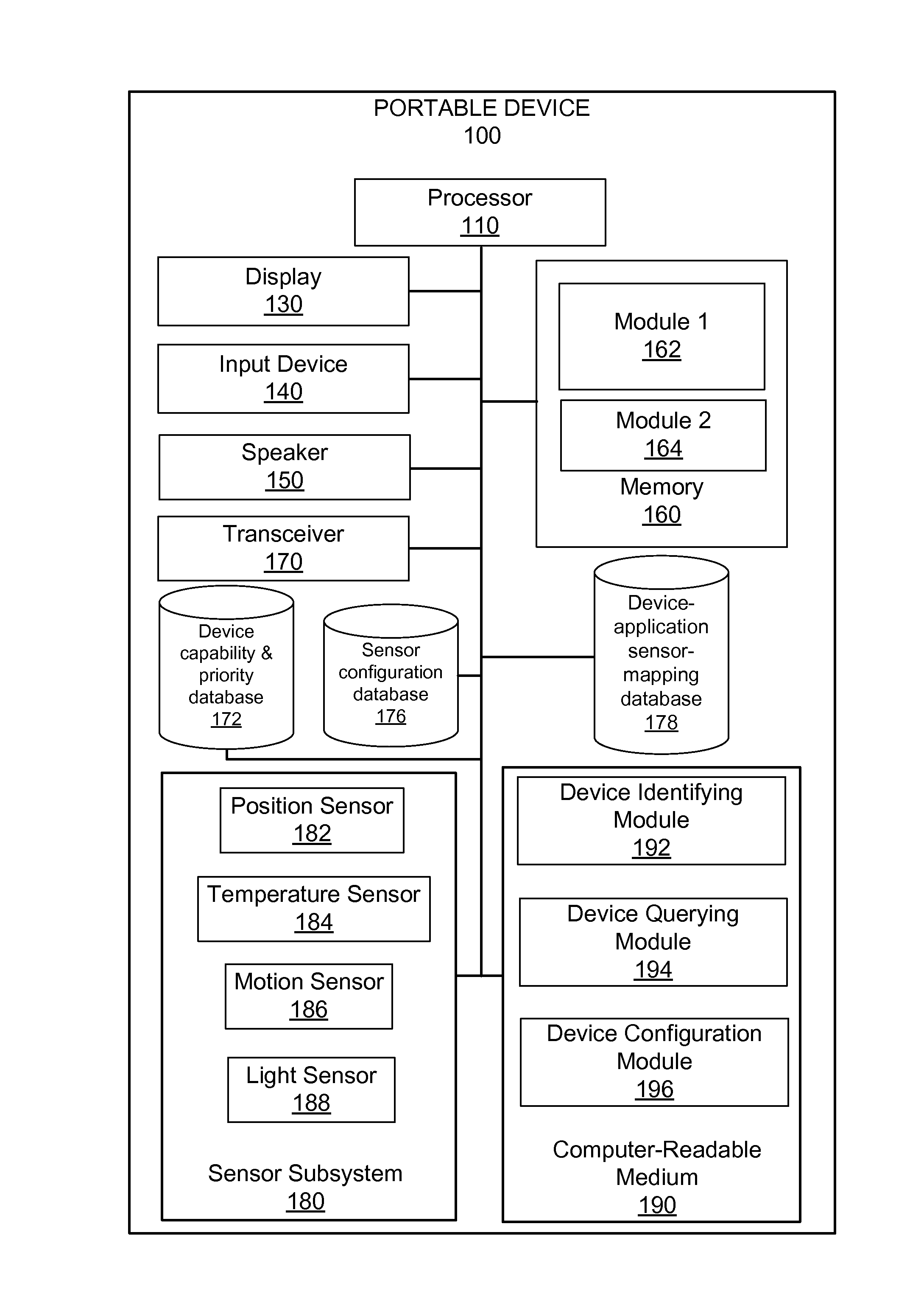
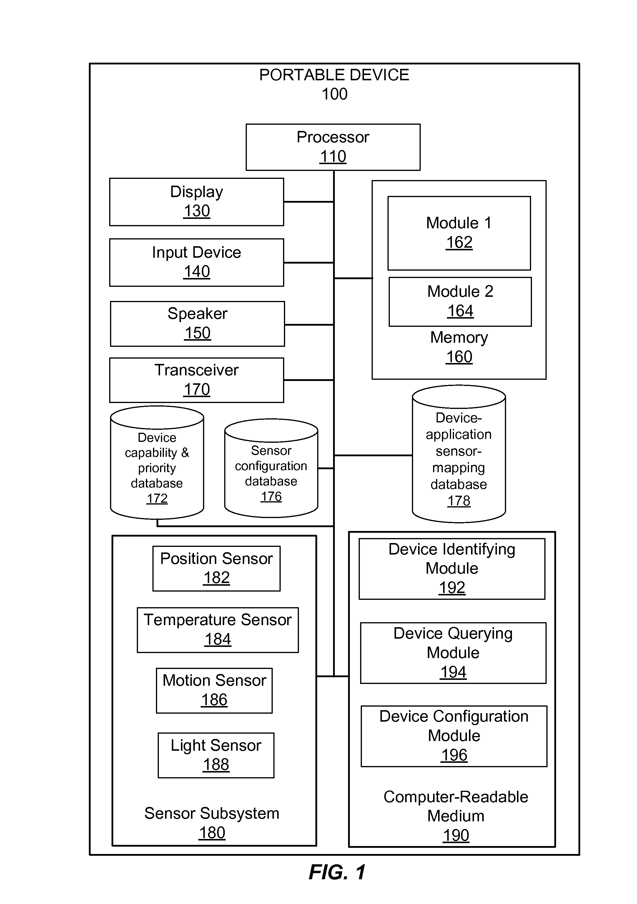
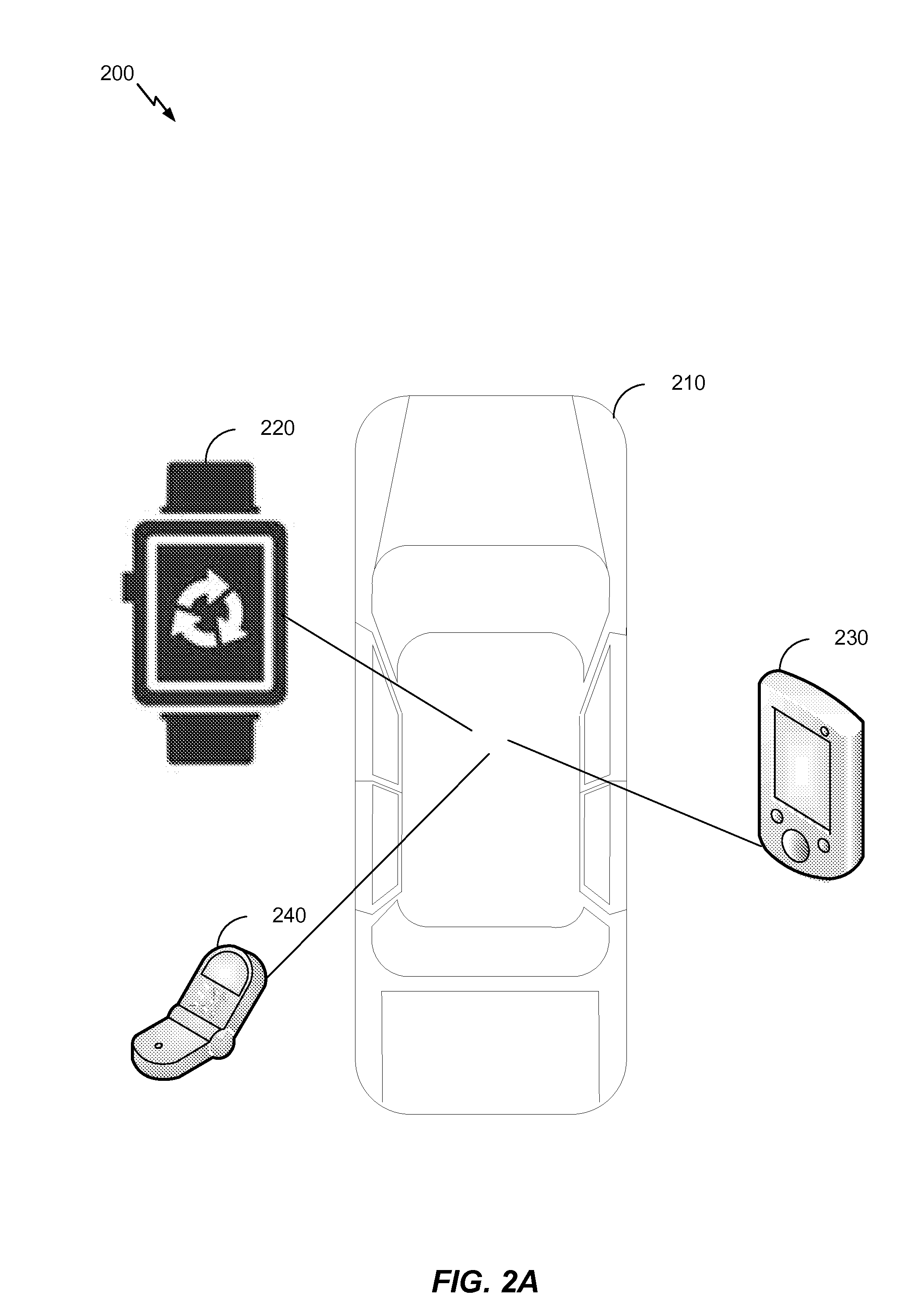
The patent is about reducing sensor redundancy in devices that have sensors. This is done by identifying devices in an area and asking them about their status or application,determining the configuration of sensors based on this information, and configuring the sensors to balance quality of service across a master device and other devices. The technical effect of this patent is to minimize the use of sensors, which can save energy and reduce interference between devices.

Problems solved by technology

The redundancy of other GPS sensors in the other devices results in a waste of power and underperformance of each device.

Method used


Image

  • Multi-device sensor subsystem joint optimization
  • Multi-device sensor subsystem joint optimization
  • Multi-device sensor subsystem joint optimization

Examples


Embodiment Construction

[0025]The detailed description set forth below in connection with the appended drawings is intended as a description of various configurations and is not intended to represent the only configurations in which the concepts described herein may be practiced. The detailed description includes specific details for the purpose of providing a thorough understanding of various concepts. However, it will be apparent to those skilled in the art that these concepts may be practiced without these specific details. In some instances, well-known structures and components are shown in block diagram form in order to avoid obscuring such concepts.

[0026]Several illustrative implementations will now be described with respect to the accompanying drawings, which form a part hereof. While particular implementations, in which one or more aspects of the disclosure may be implemented, are described below, other implementations may be used and various modifications may be made without departing from the sco...


PUM


Abstract

A system and method for reducing sensor redundancy in sensor-equipped devices includes identifying, via a master device, at least one device within an area. The at least one device is queried to determine at least one of a device status or application status for the at least one device. A configuration of one or more sensors within the at least one device based at least in part on the querying is determined. The one or more sensors within the at least one device is configured to balance quality of service across the master device and the at least one device, based at least in part on the determining.

Description

BACKGROUND[0001]The present disclosure relate generally to sensor-equipped devices, and more particularly, to methods and apparatuses for reducing and / or managing sensor redundancy in sensor-equipped devices.[0002]Devices today include many sensors that are common across devices. For instance, sensors such as GPS, accelerometer, camera, microphone, etc. are typically present in multiple device types including, cell phones, tablet computers, smart glass, smart watch, smart shoes, etc. Often times, only a single sensor from an individual device is needed to obtain a measurement (e.g., GPS coordinates). The redundancy of other GPS sensors in the other devices results in a waste of power and underperformance of each device. Accordingly, a need exists to optimize these various devices in the vicinity of a person to operate harmoniously by their sensors working in unison.BRIEF SUMMARY[0003]In some implementations, a method for reducing sensor redundancy in sensor-equipped devices includes...

Claims


Application Information

Patent Timeline
IPC IPC(8): H04L12/24H04L29/08
CPCH04L41/0823H04L41/12H04L67/12G06F1/3206G06F1/3234H04L12/403H04W52/0212H04W52/0261H04W4/02H04W52/0274H04W56/0015Y02D30/70H04L41/0853H04W4/029H04W8/005H04W8/22H04W24/02H04W84/18
Inventor JOHN ARCHIBALD, FITZGERALDRABII, KHOSRO MOHAMMAD
Owner QUALCOMM INC
Learn More