On-board device, signaling system, and control method of moving vehicle
a technology of signaling system and moving vehicle, which is applied in the direction of vehicle position/course/altitude control, process and machine control, instruments, etc., can solve the problems of high cost, large space of devices, and large load of each device, so as to reduce the introduction cost, reduce the space of devices and so on, and reduce the effect of introduction cos
- Summary
- Abstract
- Description
- Claims
- Application Information
AI Technical Summary
Benefits of technology
Problems solved by technology
Method used
Image
Examples
first embodiment
1. Configuration
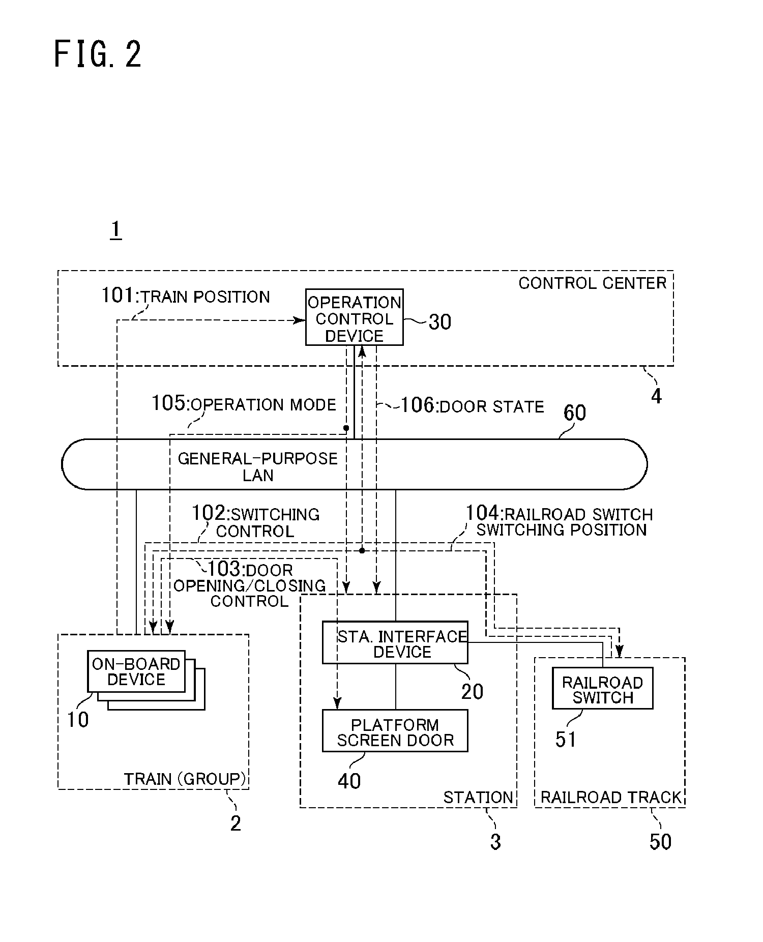
[0054]The configuration of a signaling system according to a first embodiment of the present invention will be described. FIG. 2 is a block diagram showing the configuration of the signaling system according to the present embodiment. The signaling system 1 is divided into sections of a control center 4, (a group of) trains 2, stations 3 and railroad tracks 50.
[0055]The control center 4 grasps an operation state of the trains 2 in the whole of railroad divisions. The control center 4 is provided with an operation control device 30. The operation control device 30 is connected with (on-board devices 10 of) the trains 2 and (station interface devices 20 of) the stations 3 through a general-purpose LAN 60 to be communicable bi-directionally. The operation control device 30 receives data of the trains 2 (e.g. train positions 101) from the trains 2, receives data of platform screen doors, train doors and railroad switches (e.g. door states 106, and railroad switch switchi...
second embodiment
[0118]The signaling system according to a second embodiment of the present invention will be described. In the present embodiment, the train interval protection in case of inter-station traveling of the train 2 in an operation with a failure (a failure mode) in the signaling system having the configuration described in the first embodiment will be described. Below, different points from the first embodiment will be mainly described.
1. Configuration
[0119]The control device of the on-board device 10 will be described.
[0120]FIG. 10 is a block diagram showing a configuration example of the traveling route securement determining section 70 of the control device of the signaling system according to the present embodiment. The traveling route securement determining section 70 is further provided with a route determining section 75 and a standby position traveling section 76 in addition to the configuration of FIG. 4A. The route determining section 75 determines a route to avoid a failure p...
third embodiment
[0149]The signaling system to according a third embodiment of the present invention will be described. In the present embodiment, in the signaling system which has the configuration described in the second embodiment, the train interval protection will be described in case of inter-station traveling of the train 2 in the normal mode in the end station section. Below, the difference points from the second embodiment will be mainly described.
1. Configuration
[0150]The configuration of the present embodiment is the same as that of the signaling system according to the second embodiment.
2. Operation
[0151]Next, the operation of the signaling system according to the present embodiment will be described. In this case, as the operation of the signaling system, the train interval protection will be described in case of inter-station traveling of the train 2 in the end station section in the normal mode.
[0152]The state of the railroad line to which the signaling system is applied will be descr...
PUM
 Abstract
Description
Claims
Application Information
 - R&D
- Intellectual Property
- Life Sciences
- Materials
- Tech Scout
- Unparalleled Data Quality
- Higher Quality Content
- 60% Fewer Hallucinations
Browse by: Latest US Patents, China's latest patents, Technical Efficacy Thesaurus, Application Domain, Technology Topic, Popular Technical Reports.
© 2025 PatSnap. All rights reserved.Legal|Privacy policy|Modern Slavery Act Transparency Statement|Sitemap|About US| Contact US: help@patsnap.com


