
Display method and display device

Active Publication Date: 2016-01-28
BOE TECH GRP CO LTD +1
View PDF17 Cites 20 Cited by
  • Summary
  • Abstract
  • Description
  • Claims
  • Application Information

AI Technical Summary

Benefits of technology

The present invention provides a display method and device with high resolution, excellent display effect, and small amount of calculation. The display content is processed to be a primary image, each virtual pixel in the primary image corresponds to an actual sub-pixel, and the display content of each sub-pixel is decided by multiple virtual sub-pixels in the primary image. This allows each sub-pixel to represent the display content of a plurality of virtual sub-pixels simultaneously, resulting in a higher resolution in visual effect and improved display effect with small amount of calculation.

Problems solved by technology

However, because of constraints in process, obviously the size of the sub-pixel cannot be unlimitedly reduced.
However, the display effect of the display panel of Pentile mode is still unsatisfactory.
Since the number of sub-pixels of certain colors is havled, the sub-pixels of various colors are distributed non-uniformly, which easily results in jagged lines, grid spots, the problem that fine content cannot be clearly displayed and the like.
Meanwhile, since a calculation mode of “layer-dividing and region-dividing” is adopted, determination of the content to be displayed by each sub-pixel requires complex calculation, thus amount of calculation is huge.

Method used


Image

  • Display method and display device
  • Display method and display device
  • Display method and display device

Examples


embodiment 1

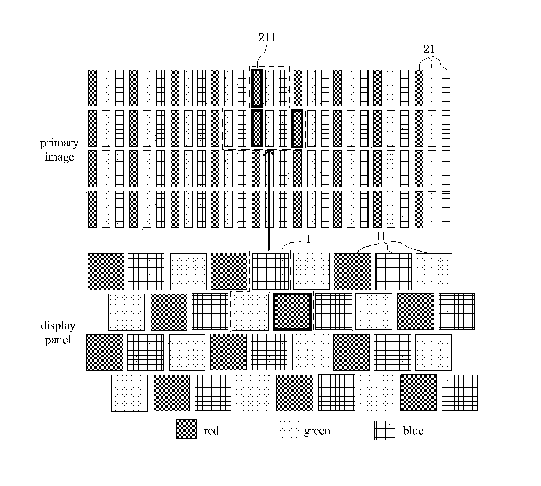
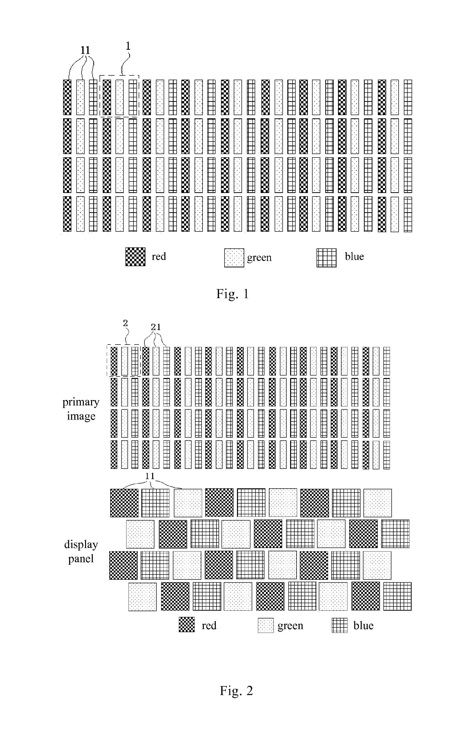
[0042]As shown in FIG. 2 to FIG. 14, the present embodiment provides a display method, which is applicable to the following display panel, the display panel comprises multiple rows of sub-pixels 11, each row of sub-pixels 11 are formed of sub-pixels 11 of various colors which are alternately and circularly arranged, and the sub-pixels 11 in each row are arranged in the same order.

[0043]Preferably, the sub-pixels 11 have three colors, for example, each sub-pixel 11 may be a red sub-pixel 11, a green sub-pixel 11 or a blue sub-pixel 11 (i.e., in a RGB mode), and in the present embodiment, introduction will be made by taking the sub-pixels 11 of three colors as an example.

[0044]That is to say, as shown in FIG. 2, in each row, three sub-pixels 11 of different colors form a cycle unit (for example, the cycle unit consisting of a red sub-pixel 11—a green sub-pixel 11—a blue sub-pixel 11), multiple such cycle units are repeatedly arranged so as to form a row of sub-pixels 11. Among the mul...

embodiment 2

[0089]The present embodiment provides a display device comprising a display panel, wherein the display panel comprises pixels arranged in a matrix, which comprises multiple rows of sub-pixels, each row of sub-pixels are formed of sub-pixels of various colors which are alternately and circularly arranged, the sub-pixels in each row are arranged in the same order, and in column direction, and sub-pixels of the same color are not adjacent, wherein the display device further comprises:

[0090]a primary image generating module for generating a primary image based on image information, the primary image is formed of virtual pixels arranged in a matrix, each of the virtual pixels is formed of sub-pixels of different colors and size of the virtual sub-pixel is the same as that of the sub-pixel of the display panel;

[0091]a display component calculating module for calculating a display component of each sub-pixel by using a primary component of sampling virtual sub-pixels of the sub-pixel, wher...


PUM


Abstract

The invention provides a display method and a display device. The display method in the invention is applicable to a display panel comprising multiple rows of sub-pixels, each row of sub-pixels are formed of sub-pixels of various colors which are alternately and circularly arranged, the sub-pixels in each row are arranged in the same order, and in column direction, sub-pixels of the same color are not adjacent, wherein the display method comprises steps of: S1, generating a primary image based on image information, the primary image is formed of virtual pixels arranged in a matrix, each virtual pixel is formed of sub-pixels of different colors and size of the virtual pixel is the same as that of the sub-pixel of the display panel; S2, calculating a display component of each sub-pixel by using primary components of sampling virtual sub-pixels of the sub-pixel.

Description

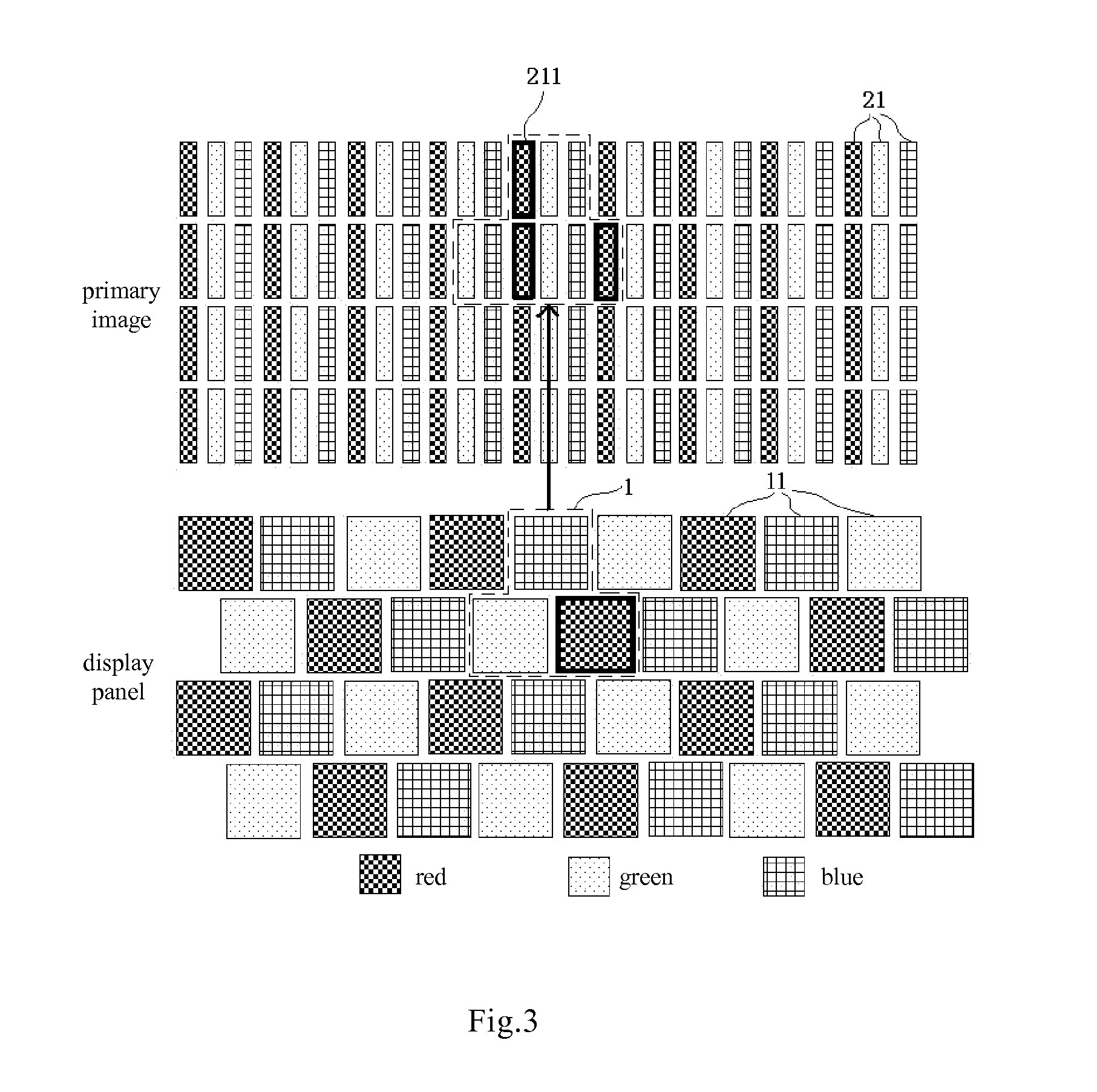
FIELD OF THE INVENTION[0001]The invention relates to the field of display technology, and particularly to a display method and a display device.BACKGROUND OF THE INVENTION[0002]As shown in FIG. 1, a conventional display panel consists of a plurality of square pixels 1, and each pixel 1 consists of three continuously arranged sub-pixels of different colors in the same row, for example, a red sub-pixel 11, a green sub-pixel 11 and a blue sub-pixel 11, wherein each sub-pixel 11 typically is rectangular strip-shaped, so that a square pixel 1 can be formed by arranging three sub-pixels 11 one by one. During displaying, display content of the three sub-pixels 11 in a pixel 1 are mixed so as to form a “display point” which is visible outside.[0003]With the development of technology, resolution of the display panel is higher and higher, that is, the number of pixels per unit area is more and more, which requires the size of each sub-pixel to be smaller and smaller. However, because of const...

Claims


Application Information

Patent Timeline
IPC IPC(8): G09G3/20
CPCG09G3/2003G09G2340/0457G09G2300/0452G09G3/20G09G2360/16
Inventor GUO, RENWEIDONG, XUE
Owner BOE TECH GRP CO LTD
Learn More