Pivotally Rotating Positioner for a Support Illuminating Multi-Task Device and the Support Illuminating Multi-Task Device

Inactive Publication Date: 2016-01-07
HUANG KUAN LUNG
View PDF6 Cites 2 Cited by
  • Summary
  • Abstract
  • Description
  • Claims
  • Application Information

AI Technical Summary

Benefits of technology

The present invention is a pivotally rotating positioner for a support illuminating multi-task device. The aim is to ensure stable electric power supplied to the light source in the light rotating arm when the arm rotates 360 degrees with respect to the body. Additionally, the invention ensures the arm can be securely locked in position at a predetermined point when rotated. The position limitation feature uses the light rotating arm as the base, the body as the rear support, and provides a stable support structure combining these two components.

Problems solved by technology

Besides, a user may watch a mobile phone or a tablet computer acting as a player for audio / video files for a quite long duration of time, typical hand-held operations may become pretty inconvenient, thus leading to elevated demands on products such as supportive frames or the like.
In addition, it is noticed that the functions of the tablet computer are gradually close to the counterparts found on notebook computers, but the input / output devices and connection ports being simplified, and the advantages may include the less complicated structure and more compact size than notebook computers, whereas the drawbacks may lie in inconvenience on input / output operations and probably insufficient connection ports upon connecting multiple external peripheral devices thereto.
However, once the mobile power supply and the supportive frame are integrated, in addition to an illuminating function, for example, thus together forming a multi-task device, it is inevitable to encounter the following problems.
Unfortunately, after many repetitive pivotal rotation tests during the research and development stage, the protrusive grains 30 made by plastic materials may be rapidly worn off, thus being completely unable to position at the aforementioned specific angles.
As for direct hard-wire connections, it may not satisfy the requirement on electrical conduction of 360 degree rotations.

Method used


Image

  • Pivotally Rotating Positioner for a Support Illuminating Multi-Task Device and the Support Illuminating Multi-Task Device
  • Pivotally Rotating Positioner for a Support Illuminating Multi-Task Device and the Support Illuminating Multi-Task Device
  • Pivotally Rotating Positioner for a Support Illuminating Multi-Task Device and the Support Illuminating Multi-Task Device

Examples


Embodiment Construction

[0031]The aforementioned and other technical contents, aspects and effects in relation with the present invention can be clearly appreciated through the detailed descriptions concerning the preferred embodiments of the present invention in conjunction with the appended drawings; moreover, in each embodiment, the same components will be denoted with similar numbers.

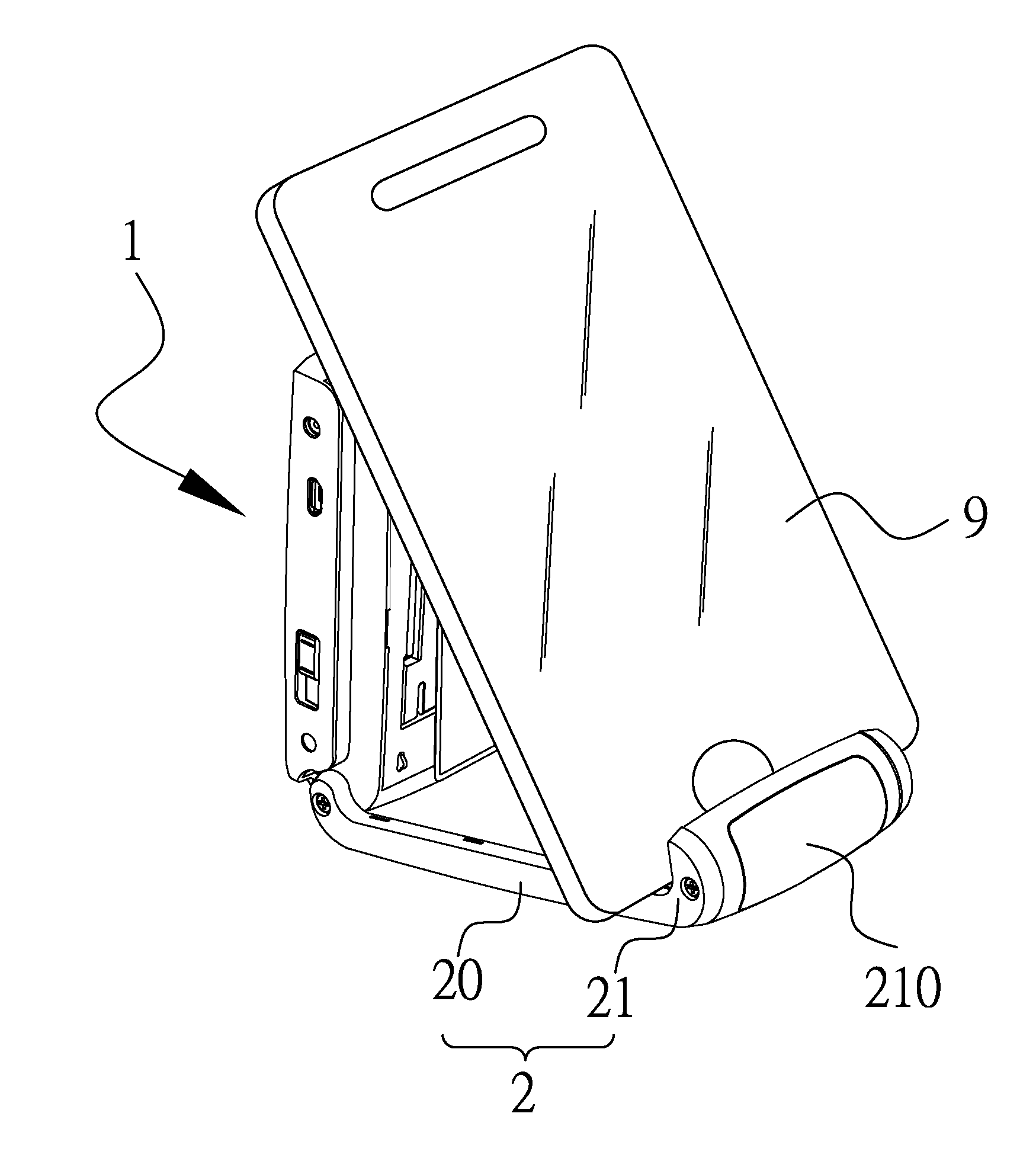
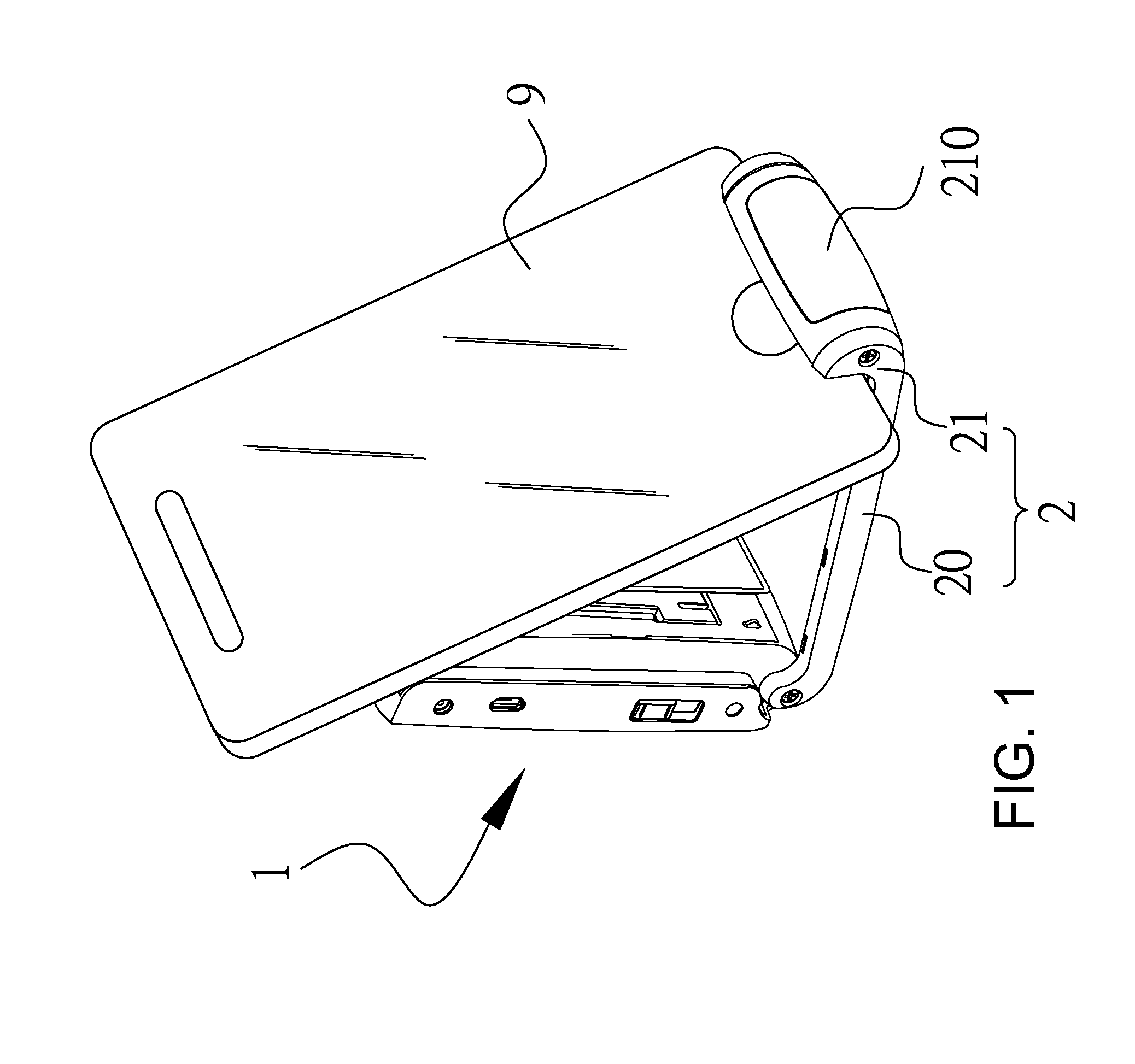
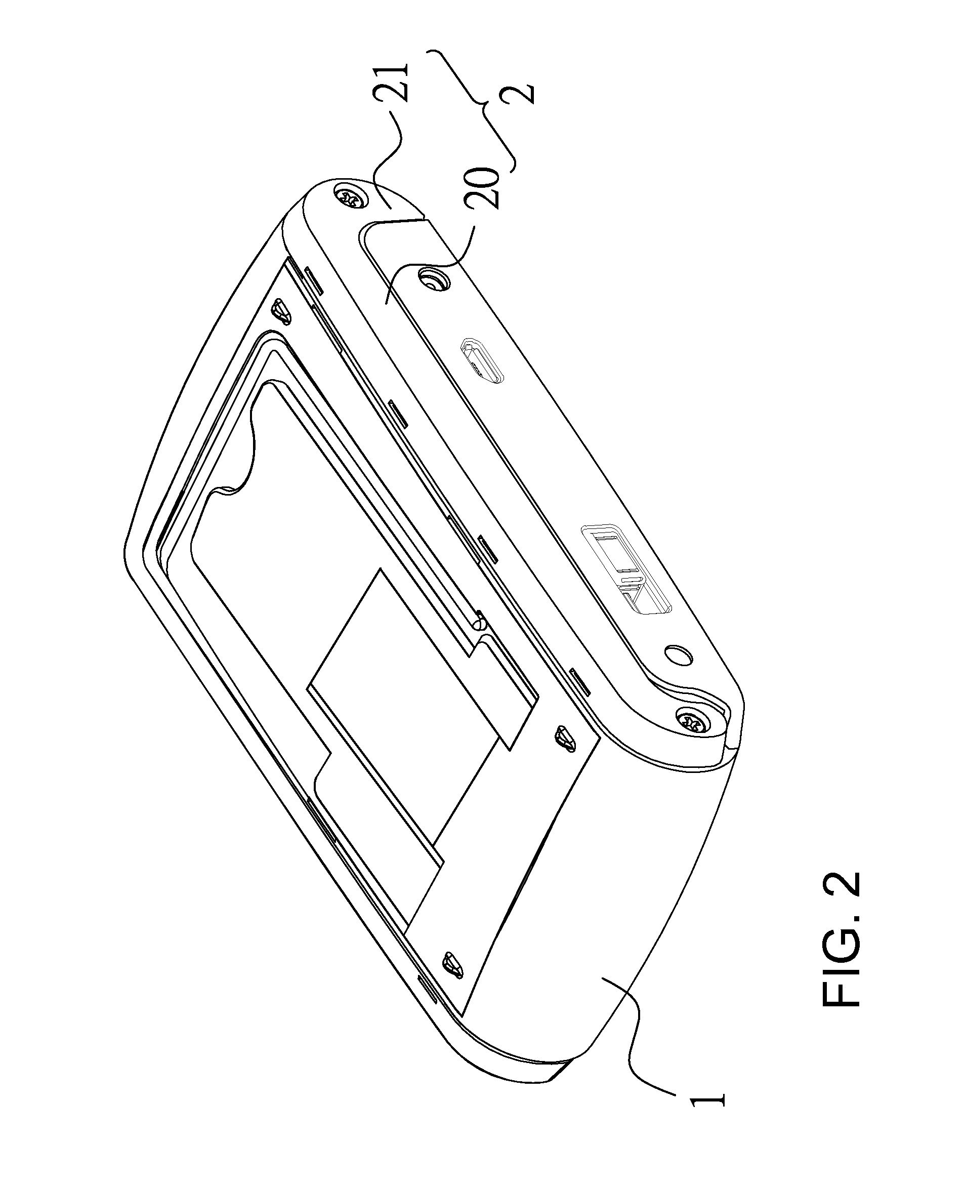
[0032]Referring to FIGS. 7 and 8, certain structures demonstrated in the present embodiment are identical to the prior support illuminating multi-task previously developed by the applicant of the present invention, which essentially comprises a body 4, a light rotating arm 5 conductively connected to the body in a fashion of pivotal rotations at variable angles, and a set of pivotally rotating positioner 6.

[0033]Herein the body 4, as the counterpart in FIG. 1, comprises a base housing 40 and a power supply assembly 42 configured as the rechargeable battery within the base housing, the base housing 40 has at least a pair of...


PUM


Abstract

A pivotally rotating positioner for a support illuminating multi-task device which can be applied to conductively connect a light rotating arm to a body in a fashion of pivotal rotations at variable angles. However, upon pivotally rotating, it is possible to compress the electrically conductive spring to prevent serious abrasions in the snapping recesses and the snapping bumps on the rotating arm case and the base housing. Moreover, by means of the elastic coercion between the electrically conductive spring and the electrically conductive pivotal axis assembly, it is possible to allow the electrical energy coming from the body to be smoothly provided to the light rotating arm via the pivotal axis and also enable a free rotation of 360 degrees of the light rotating arm with respect to the body while maintaining the illumination effect.

Description

CROSS REFERENCE TO RELATED APPLICATION[0001]This application claims the benefit of priority to TW 103211858, filed on Jul. 3, 2014 with the Intellectual Property Office of the Republic of China, Taiwan, the entire specification of which is incorporated by reference herein.FIELD OF THE INVENTION[0002]The present invention generally relates to a pivotally rotating positioner; in particular, the present invention relates to a pivotally rotating positioner for a support illuminating multi-task device and the support illuminating multi-task device utilizing the pivotally rotating positioner.BACKGROUND OF THE INVENTION[0003]Currently, mobile phones and tablet computers are more and more popular, and their functions are no longer limited to purely telephone calls, but already evolve from earlier simple communications into audio / video transmissions. Although this type of functions are widely accepted by numerous users, electric power consumptions thereof also increase significantly at the s...

Claims


Application Information

Patent Timeline
IPC IPC(8): E05D11/00E05D11/06E05D11/10F16M11/38F21V21/26F21V33/00H04M1/04
CPCE05D11/0081F16M11/38H04M1/04E05D11/06E05D11/1007F21Y2101/02F21V33/0048F21V21/26E05D2011/1035F21W2131/30E05D11/1028E05D11/1078H04M1/0214F21Y2115/10F16M13/00F16M13/022E05Y2999/00
Inventor HUANG, KUAN-LUNG
Owner HUANG KUAN LUNG
Why Eureka
Try Eureka