
Modular stimulator for treatment of back pain, implantable RF ablation system and methods of use

a technology of modulator and back pain, which is applied in the field of modulator for back pain, implantable rf ablation system and methods of use, can solve the problems of overloading of structures, disc degeneration, ligament damage, etc., and achieve the effects of restoring neural drive, reducing pain, and rehabilitating spinal stability

Active Publication Date: 2015-12-31
MAINSTAY MEDICAL
View PDF6 Cites 63 Cited by
  • Summary
  • Abstract
  • Description
  • Claims
  • Application Information

AI Technical Summary

Benefits of technology

The system provides sustained pain relief and improved muscle rehabilitation by simultaneously addressing pain and muscle instability, reducing the need for frequent interventions and enhancing patient comfort during therapy.

Problems solved by technology

Over time, dysfunction of the spinal stabilization system can lead to instability and abnormal movement of the spine, resulting in overloading of structures when the spine moves beyond its neutral zone.
High loads can lead to inflammation, disc degeneration, ligament damage, facet joint degeneration, and muscle fatigue, all of which can result in pain.
If pain persists after physical therapy or surgical intervention to prevent the abnormal motion that leads to pain, few options are available for relief.
While this technique can be effective, it provides only short term relief as nerve fibers may regenerate over time, and generally the procedure must be repeated approximately every six months to maintain effective pain control.
The key drawback with all of the previously known electrical stimulation techniques that seek to block the pain signals (TENS, PENS, SCS and RF Ablation of the nerves) is that relief, if obtained, is usually only temporary, and repeated or continuous therapies are needed.
While the stimulator system described in the Sachs application seeks to rehabilitate the multifidus and restore neural drive, it does not provide relief of the pain during the application of the therapy.
Thus, it is possible that for some patients the effectiveness of the therapy may be hindered by the continuation of pain, which may interfere with restoration of neural drive to the muscle or impede the patient's ability to tolerate the therapy.

Method used


Image

  • Modular stimulator for treatment of back pain, implantable RF ablation system and methods of use
  • Modular stimulator for treatment of back pain, implantable RF ablation system and methods of use
  • Modular stimulator for treatment of back pain, implantable RF ablation system and methods of use

Examples


Embodiment Construction

[0040]System Overview

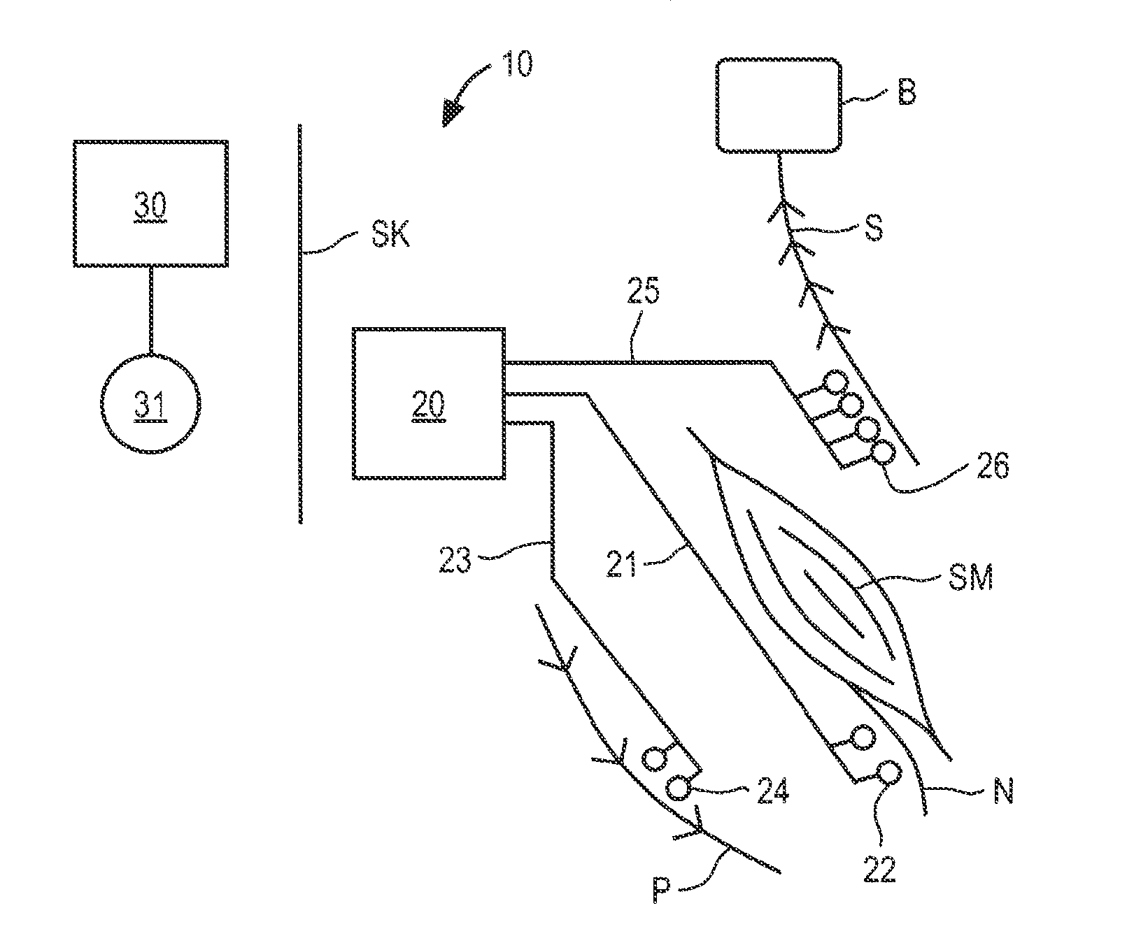
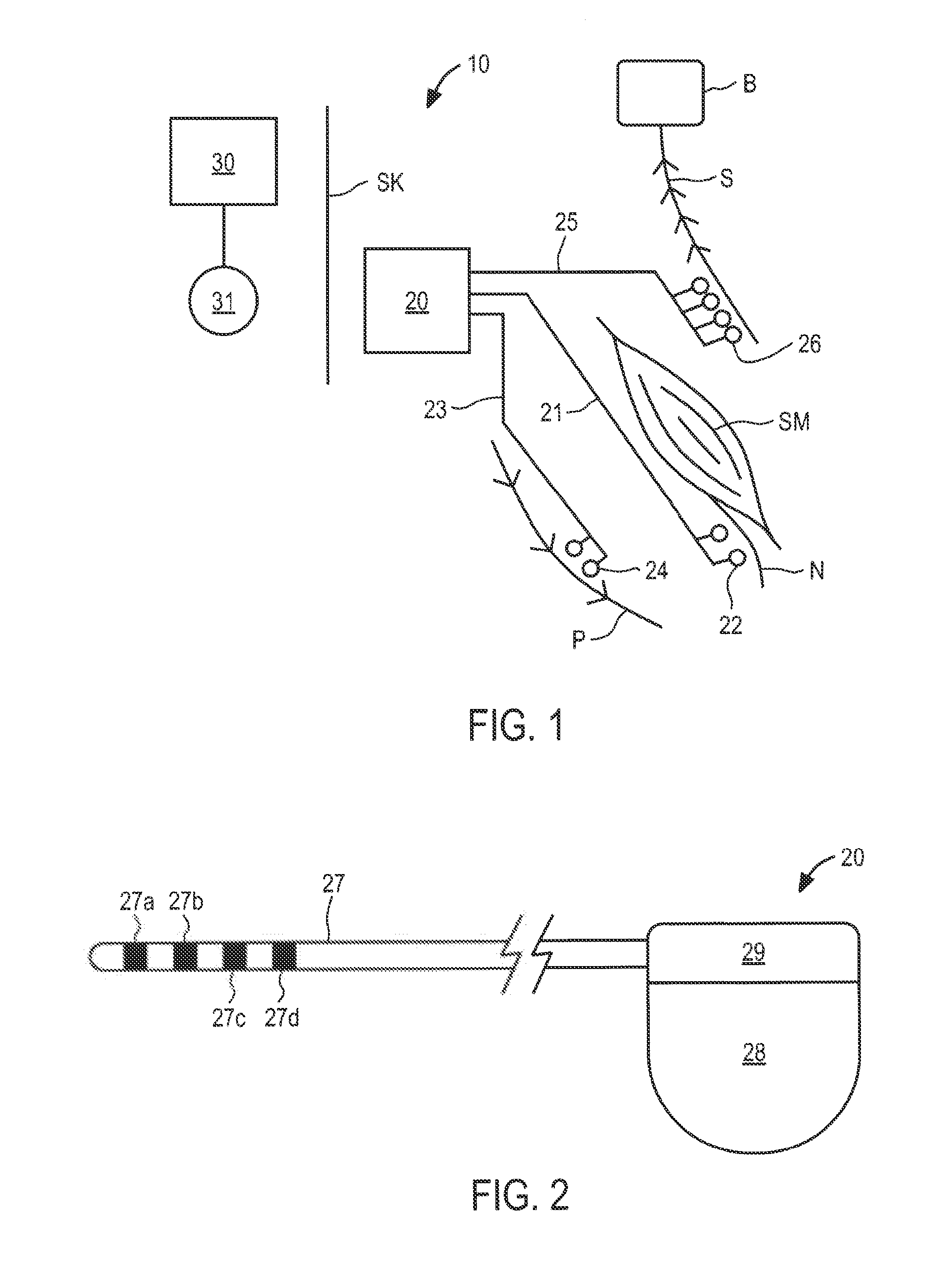
[0041]Referring to FIG. 1, an overview of an exemplary stimulator system constructed in accordance with the principles of the present invention is provided. In FIG. 1, components of the system are not depicted to scale on either a relative or absolute basis. Stimulator system 10 comprises implantable stimulator 20 and external control system 30. In the illustrated embodiment, software may be installed and run on a conventional laptop computer, and used by the patient's physician to program external control system 30 and / or to provide programming that is communicated by external control system 30 to stimulator 20. During patient visits, external system 30 may be coupled, either wirelessly or using a cable, to the physician's computer to download for review data stored on stimulator 20, or to adjust the operational parameters of the stimulator.

[0042]In FIG. 1 implantable stimulator 20 is connected to a plurality of electrode leads. Illustratively, electrode lead 2...


PUM


Abstract

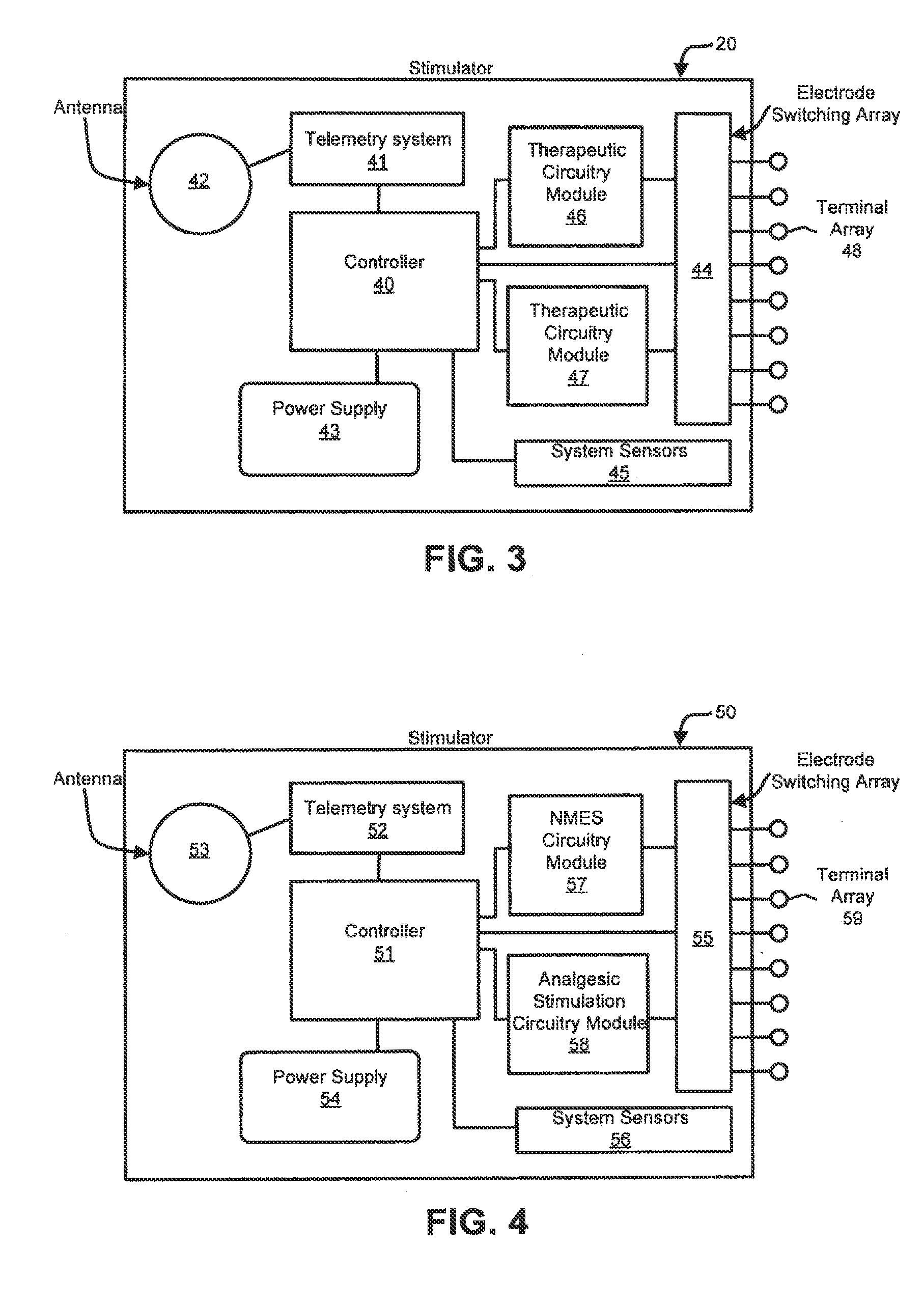
Apparatus and methods for treating back pain are provided, in which an implantable stimulator is configured to communicate with an external control system, the implantable stimulator providing a neuromuscular electrical stimulation therapy designed to cause muscle contraction to rehabilitate the muscle, restore neural drive and restore spinal stability; the implantable stimulator further including one or more of a number of additional therapeutic modalities, including a module that provides analgesic stimulation; a module that monitors muscle performance and adjusts the muscle stimulation regime; and / or a module that provides longer term pain relief by selectively and repeatedly ablating nerve fibers. In an alternative embodiment, a standalone implantable RF ablation system is described.

Description

I. REFERENCE TO RELATED APPLICATIONS[0001]This application claims the benefit of priority of U.S. provisional application Ser. No. 61 / 339,957, filed Mar. 11, 2010.II. FIELD OF THE INVENTION[0002]This application relates to apparatus and method for treating back pain by combining circuitry for providing neuro-muscular electrical stimulation (NMES) therapy with circuity for providing analgesic stimulation, performance monitoring and feedback, and / or selective ablation.III. BACKGROUND OF THE INVENTION[0003]The human back is a complicated structure including bones, muscles, ligaments, tendons, nerves and other structures. The spinal column consists of interleaved vertebral bodies and intervertebral discs. These joints are capable of motion in several planes including flexion-extension, lateral bending, axial rotation, longitudinal axial distraction-compression, anterior-posterior sagittal translation, and left-right horizontal translation. The spine provides connection points for a comp...

Claims


Application Information

Patent Timeline
Patent Type & Authority Applications(United States)
IPC IPC(8): A61N1/36A61N1/372A61N1/05
CPCA61B18/1492A61B2017/00221A61B2018/00339A61B2018/00577A61B2018/124A61B2034/2048A61N1/0551A61N1/06A61N1/36042A61N1/36071A61N1/37211A61B2018/1467A61N1/36062A61N1/36146A61N1/36057A61N1/36003
Inventor CROSBY, PETER ANDREWSACHS, DANRAWAT, PRASHANT BRIJMOHANSINGHSHIROFF, JASON ALANHEEMELS, JOHANNES PETRUS
Owner MAINSTAY MEDICAL
Learn More