
Vehicle to vehicle wireless communication apparatus with potential crash warning

a wireless communication and vehicle technology, applied in the direction of variable traffic instructions, road vehicle traffic control, instruments, etc., can solve the problems of low radio frequency likely to interfere with communication between neighboring vehicles, communication failure may occur with high possibility,

Active Publication Date: 2015-12-03
ALPINE ELECTRONICS INC
View PDF0 Cites 44 Cited by
  • Summary
  • Abstract
  • Description
  • Claims
  • Application Information

AI Technical Summary

Benefits of technology

This patent describes a wireless communication device for vehicle-to-vehicle communication in a first vehicle. The device receives sensory information about the vehicle's position and direction, and map data that includes pre-calculated route information. The device calculates a potential signal pattern based on this information and controls the radio intensity, frequency, and direction to transmit the signal. The device then produces a radio signal with the assigned radio intensity, frequency, and direction. The radio signal is then radiated from the vehicle's antennas. The technical effects of this patent include improved wireless communication for vehicle-to-vehicle communication and better control of the radio signal based on driving status information.

Problems solved by technology

Frequently, in vehicle-to-vehicle and vehicle-to-infrastructure (V-to-X) communication, communication failure may occur with high possibility mainly because of weak radio propagation when obstacles are located on a communication path.
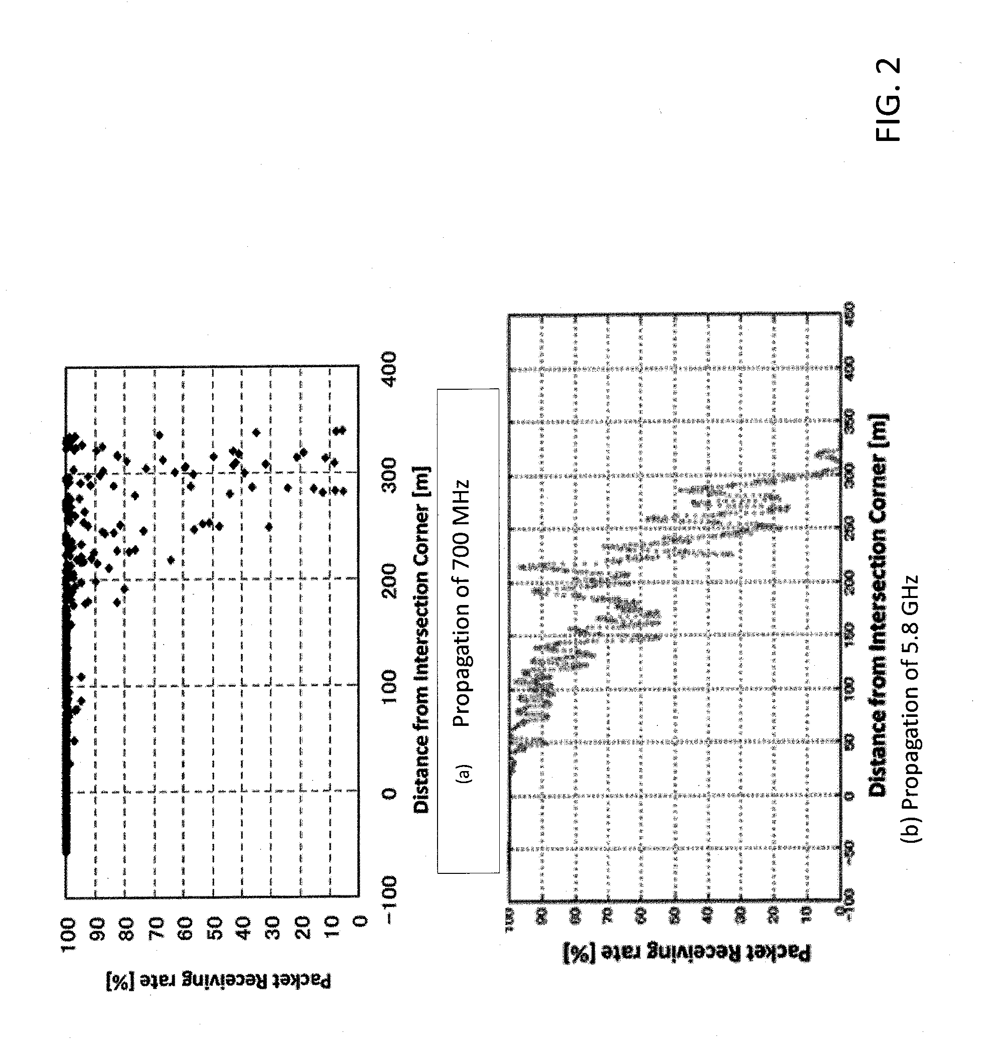
However, too strong radio propagation by large radio output intensity or low radio frequency is likely to interfere to communications between neighboring vehicles (i.e. in freeways or urban intersections) or other communications with adjacent frequencies.

Method used


Image

  • Vehicle to vehicle wireless communication apparatus with potential crash warning
  • Vehicle to vehicle wireless communication apparatus with potential crash warning
  • Vehicle to vehicle wireless communication apparatus with potential crash warning

Examples


Embodiment Construction

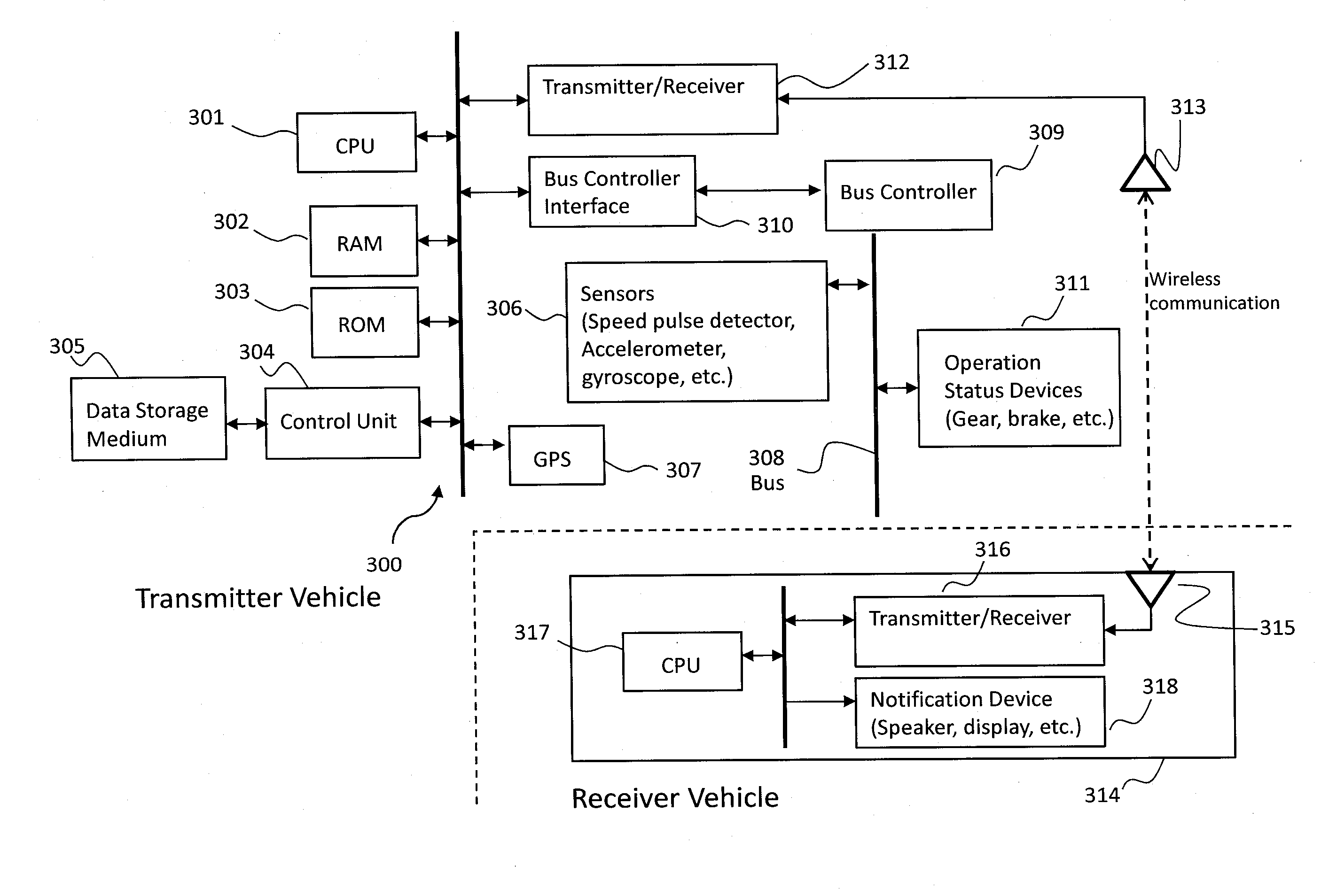
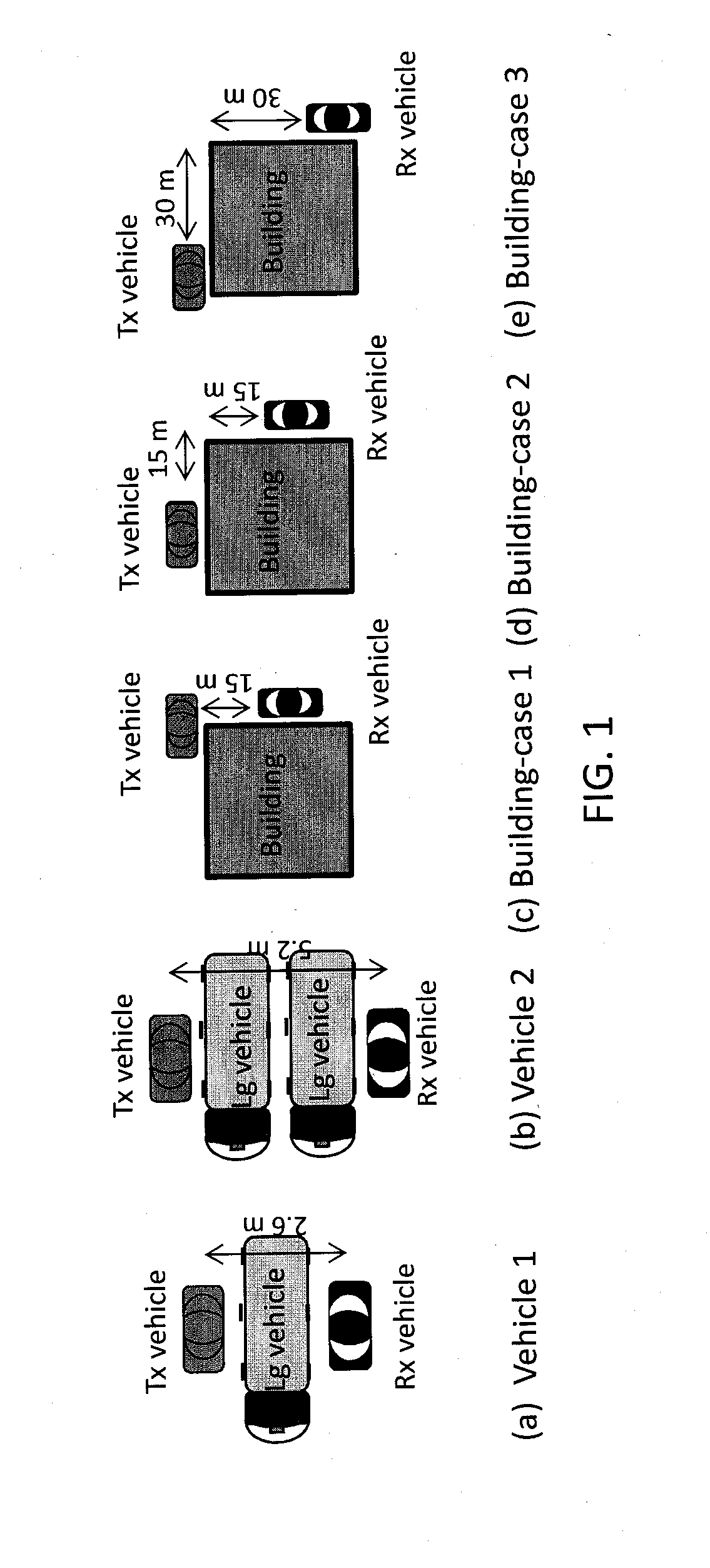
[0023]Various embodiments for a wireless communication device and method for vehicle-to-vehicle communication in a vehicle with another vehicle will be described hereinafter with reference to the accompanying drawings. Unless defined otherwise, all technical and scientific terms used herein have the same meaning as commonly understood to one of ordinary skill in the art to which present disclosure belongs. Although the description will be made mainly for the case where the wireless communication device and method for vehicle-to-vehicle communication in the vehicle with another vehicle, any methods, devices and materials similar or equivalent to those described, can be used in the practice or testing of the embodiments. All publications mentioned are incorporated by reference for the purpose of describing and disclosing, for example, the designs and methodologies that are described in the publications which might be used in connection with the presently described embodiments. The pub...


PUM


Abstract

A wireless communication device for vehicle-to-vehicle communication includes a vehicle positioning module that uses sensors and detects a current position and a direction of the vehicle. In a map matching, pre-calculated route information and road network information based on the current position are retrieved from map data and a current link of the vehicle is identified and a potential signal pattern is determined regarding a position of next intersection and the road network information based on the current position, the direction of the vehicle and the current link. Based on the potential signal pattern, radio characteristics including a level of intensity, a frequency, and a direction are assigned. A transmitter produces a radio signal of the radio characteristics carrying the current position, the speed and the direction of the vehicle. An antenna module converts the radio signal from the transmitter into radio waves and radiates the radio waves.

Description

BACKGROUND[0001]1. Field[0002]The present disclosure relates to a device and method of wireless communication for vehicle-to-vehicle (V2V) communication in a vehicle. More specifically, embodiments in the present disclosure relate to a device and method of wireless V2V communication with switching among a plurality of radio transmission configurations depending on assumed a positional relationship between a signal transmitting vehicle and a signal receiving vehicle, and signal environmental factors, such as potential obstacles and geographical surroundings.[0003]2. Description of the Related Art[0004]Frequently, in vehicle-to-vehicle and vehicle-to-infrastructure (V-to-X) communication, communication failure may occur with high possibility mainly because of weak radio propagation when obstacles are located on a communication path. Radio propagation degradation has been believed to be relatively large when any large obstacles are located on a communication path, thus an increase of r...

Claims


Application Information

Patent Timeline
IPC IPC(8): G08G1/0967
CPCG08G1/096791G08G1/096716G08G1/162G08G1/163
Inventor ONISHI, HIROFUMI
Owner ALPINE ELECTRONICS INC
Learn More