
System and method for controlling voltage at point of common coupling of wind farm

a technology of common coupling and control method, which is applied in the direction of electric generator control, machines/engines, mechanical equipment, etc., can solve the problems of unavoidable big overshoot, unavoidable sub>ref /sub> of the point of common coupling, and insufficient utilization of available reactive power and active power according to the wind speed in each wind turbin

Inactive Publication Date: 2015-11-26
IND COOP FOUND CHONBUK NAT UNIV
View PDF1 Cites 36 Cited by
  • Summary
  • Abstract
  • Description
  • Claims
  • Application Information

AI Technical Summary

Benefits of technology

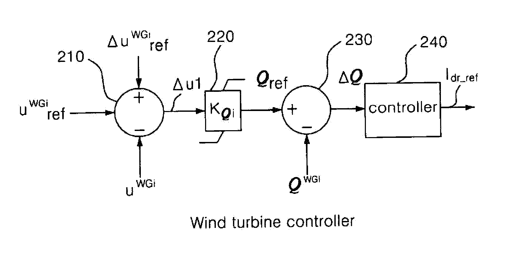
The present invention provides a system and method for controlling voltage at a point of common coupling in a wind farm. The system includes a wind farm controller, multiple wind turbine controllers, and wind turbines. The wind farm controller calculates a voltage error value and a compensation reference voltage value, while the wind turbine controllers calculate a second voltage error value and a reactive power compensation value based on the voltage error value. The wind turbines then inject a reactive current into the power grid to quickly recover the voltage. The technical effect of the invention is to provide a system and method for controlling voltage at a point of common coupling in a wind farm that can quickly recover from disturbances in the power system.

Problems solved by technology

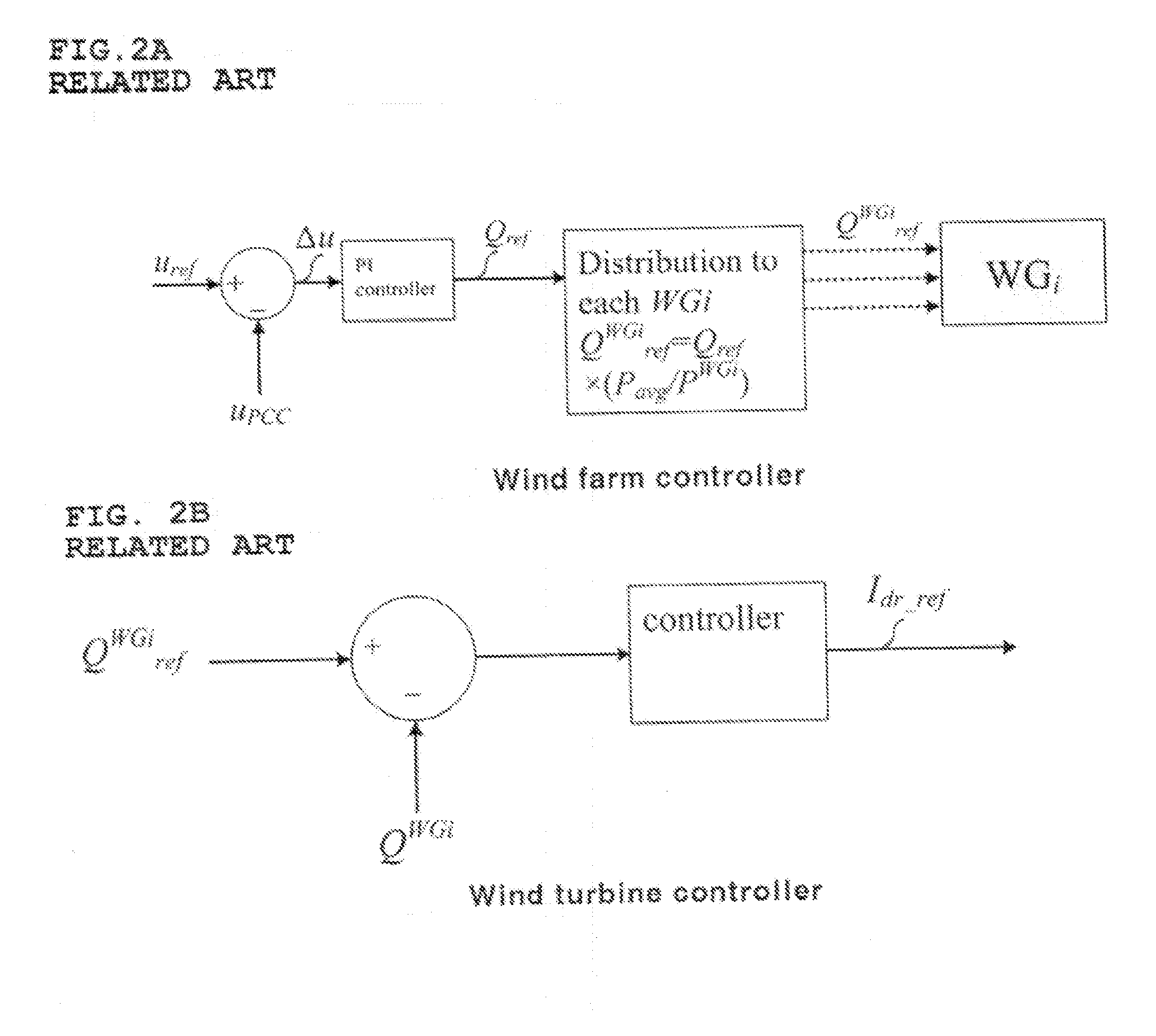
However, when the voltage control method of the first conventional technique according to FIG. 2 is utilized, although it is advantageous in that voltage upcc of the point of common coupling (PCC) can be promptly recovered to the reference voltage uref, there is a problem in that a big overshoot is unavoidable since excessive reactive power more than needed is injected into the power grid when a high weighting factor is multiplied.
However, when the voltage of a point of common coupling is controlled according to a second conventional technique, since a reactive current compensation value Idr—ref is calculated by equally multiplying only the same slope kQi as shown in FIG. 4 without considering the active energy of each wind turbine changing by the wind speed or the like with time, there is a limit in that available reactive power changing together with the active power changing according to the wind speed in each wind turbine cannot be sufficiently utilized, and, as a result, there is a problem in that generation of an error in the neighborhood of the reference voltage uref of the point of common coupling is unavoidable in a steady state after a disturbance.

Method used


Image

  • System and method for controlling voltage at point of common coupling of wind farm
  • System and method for controlling voltage at point of common coupling of wind farm
  • System and method for controlling voltage at point of common coupling of wind farm

Examples


Embodiment Construction

[0037]The embodiments disclosed in this specification should not be interpreted or used to limit the scope of the present invention. It is natural to those skilled in the art that descriptions including the embodiments of the present invention have a variety of applications. Accordingly, certain embodiments specified in the detailed descriptions of the present invention are merely provided for illustrative purposes for better explanation of the present invention and are not intended to limit the scope of the present invention to the embodiments. In describing the present invention, if already known functions or specific descriptions of constitutions related to the present invention may make the spirit of the present invention unclear, detailed descriptions thereof will be omitted.

[0038]Embodiments of the present invention will be hereafter described in more detail with reference to the accompanying drawings.

[0039]FIGS. 5A and 5B are views schematically showing a system for controlli...


PUM


Abstract

A system and method for controlling voltage at a point of common coupling of a wind farm including a plurality of wind turbines is provided. The method includes: calculating a first voltage error value, which is a difference between a reference voltage value of the point of common coupling and an actual voltage value of the point of common coupling; calculating a compensation reference voltage value based on the first voltage error value; calculating a second voltage error value by subtracting a voltage value of an output terminal of a wind turbine from a sum of a reference voltage value of the wind turbine and the compensation reference voltage value; calculating a reactive power compensation value corresponding to the second voltage error value; and injecting a reactive current corresponding to the reactive current compensation value into a power grid.

Description

BACKGROUND OF THE INVENTION[0001]1. Field of the Invention[0002]The present invention relates to a control method for maintaining point of common coupling (PCC) voltage of a wind farm, and more specifically, to a method of promptly recovering PCC voltage by supplying each wind turbine with a portion of reactive power needed for recovering the voltage in proportion to available reactive power when a disturbance such as voltage reduction occurs at a bus close to the point of common coupling.[0003]2. Background of the Related Art[0004]In order to continue stable operation of a power grid, bus voltages of a system should be maintained within an allowed range when a relatively small disturbance such as a load change occurs in the system. In addition, when a relatively big disturbance such as a short circuit fault of a power grid occurs, voltages of the system bus should be promptly recovered within the allowed range after the fault is removed, as well as while the fault lasts. When a vol...

Claims


Application Information

Patent Timeline
IPC IPC(8): F03D9/00F03D7/00
CPCF03D7/00F03D9/005H02J3/16F03D7/048F03D9/257H02J2300/28H02J3/381Y02E10/72Y02E10/76Y02E40/30H02J3/50
Inventor KANG, YONG CHEOLKIM, JINHOPARK, GEON
Owner IND COOP FOUND CHONBUK NAT UNIV
Learn More