
Phase conversion device for electromagnetic wave

a phase conversion device and electromagnetic wave technology, applied in the field of phase conversion devices for electromagnetic waves, can solve the problems of electromagnetic waves being released, mobile phones are harmful, information obtained through the internet is not always positive, etc., and achieve the effect of favorable numerical values, and reducing the influence of electromagnetic waves in a wider rang

Active Publication Date: 2015-11-19
WAKITANI KIYOTAKA
View PDF1 Cites 0 Cited by
  • Summary
  • Abstract
  • Description
  • Claims
  • Application Information

AI Technical Summary

Benefits of technology

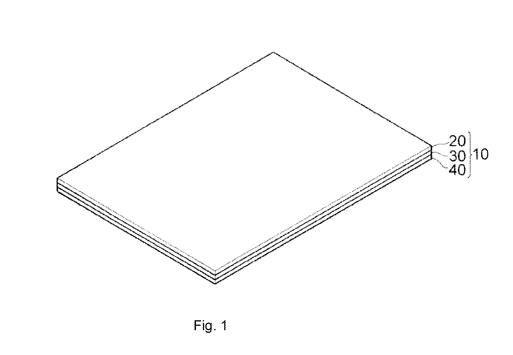
The present invention is a phase conversion device that converts electromagnetic waves into right-handed and left-handed circularly polarized waves while reducing electric and magnetic influences. The device includes three layers with specific wavelength plates that convert the electromagnetic waves. This conversion results in a favorable outcome in an O-ring test, which measures the effect of the electromagnetic waves on a living body. The device can be attached to an electrical machine or used in an oscillation circuit. It can also be replaced with a transparent member such as OPP tape to reduce costs.

Problems solved by technology

However, information obtained through the Internet is not always positive with respect to the electromagnetic waves and there are many reports abroad that mobile phones are harmful.
In addition, a report that the electromagnetic waves are harmful has also been released by the WHO.
It is often seen that one's shoulder becomes stiff and the eyes become fatigued when using a personal computer.
However, there is also a tendency that the muscles become stiff and the cerebral blood flow is reduced due to the electromagnetic waves.
In this manner, the fact that electromagnetic waves are hardly regulated while there is a concern of an influence of the electromagnetic waves on human bodies is caused by unclear objective evidence.

Method used


Image

  • Phase conversion device for electromagnetic wave
  • Phase conversion device for electromagnetic wave
  • Phase conversion device for electromagnetic wave

Examples


Embodiment Construction

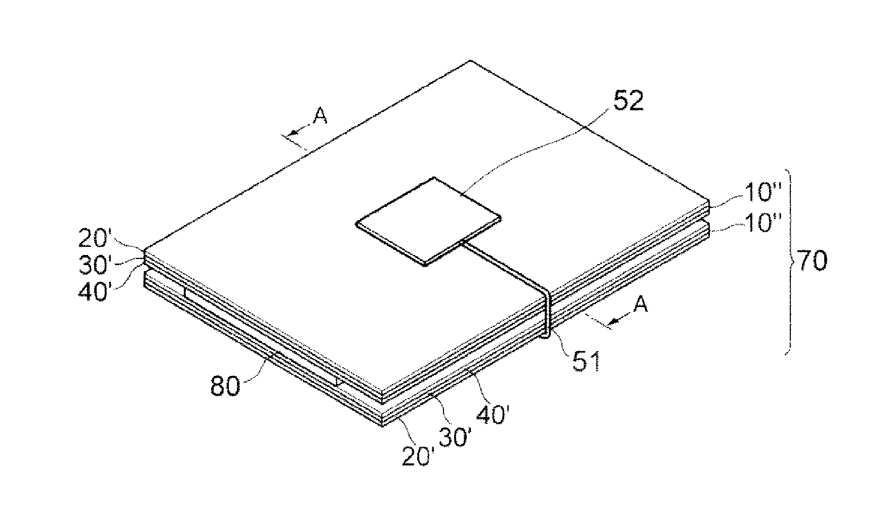
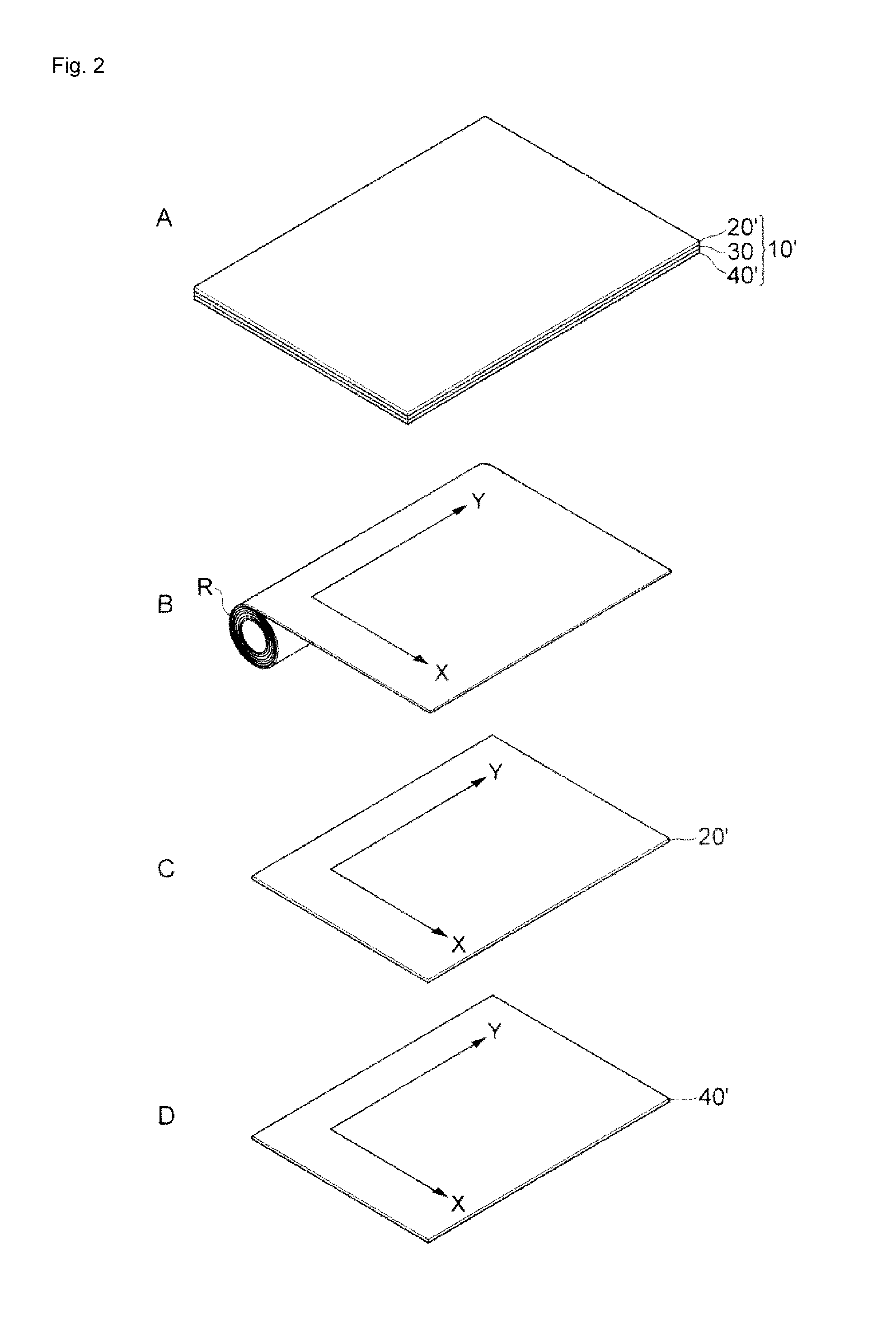
[0016]Hereinafter, the present invention will be described in more detail with reference to the embodiment shown in the drawings. FIG. 1 is a perspective view of a phase conversion device for an electromagnetic wave according to the present invention. A of FIG. 2 is a perspective view of another Example of a phase conversion device for an electromagnetic wave according to the present invention. B of FIG. 2 is a state view in which a sheet is drawn from a roll. C of FIG. 2 is a perspective view of a transparent member. D of FIG. 2 is a perspective view of a transparent member. A of FIG. 3 is a perspective view of still another example of a phase conversion device for electromagnetic wave according to the present invention. B of FIG. 3 is a state view in which a sheet is drawn from a roll. C of FIG. 3 is a perspective view of a transparent member. D of FIG. 3 is a perspective view of a transparent member. E of FIG. 3 is a perspective view of a transparent member. FIG. 4 is a perspecti...


PUM


Abstract

A phase conversion device, which converts an electromagnetic wave into a right-handed circularly polarized wave and a left-handed circularly polarized wave to attenuate electric and magnetic effects, includes first, second, and third layers. The first layer includes a ½ lambda wavelength plate. The second layer includes a ¼ lambda wavelength plate. The third layer includes a ½ lambda wavelength plate. The device is effective to reduce an influence of the electromagnetic wave on an electric field and a magnetic field. The device may be portable and useable to reduce an influence of electromagnetic waves on a human body.

Description

TECHNICAL FIELD[0001]The present invention relates to a device for subjecting an electromagnetic wave of a subject to phase conversion to reduce electric and magnetic influences which are affected by the electromagnetic wave of the above-described subject.BACKGROUND ART[0002]Electromagnetic waves still continue to increase due to so-called factors, such as progress of all electrification, spread of hybrid cars or personal computers, and transition to ground digitization, which overlap each other. It has been officially known that there is no actual harm in such electromagnetic waves. However, information obtained through the Internet is not always positive with respect to the electromagnetic waves and there are many reports abroad that mobile phones are harmful. Moreover, many books that discuss the harmfulness of the electromagnetic waves have been published. In addition, a report that the electromagnetic waves are harmful has also been released by the WHO. It is often seen that on...

Claims


Application Information

Patent Timeline
Patent Type & Authority Applications(United States)
IPC IPC(8): H01Q15/24H01Q1/52
CPCH01Q1/526H01Q15/244G02B5/3083H01Q3/46H01Q15/0006H01Q17/00H01Q19/062
Inventor WAKITANI, KIYOTAKA
Owner WAKITANI KIYOTAKA
Learn More