
Hearth pad

a technology of earth pad and spherical plate, which is applied in the field of earth pad, can solve the problems of inconvenient installation, inconvenient handling, and inconvenient installation, and achieve the effects of convenient installation, improved thermal insulation properties, and low cos

Inactive Publication Date: 2015-11-19
HESTIA INC D B A AMERICAN PANEL HEARTH PROD
View PDF1 Cites 1 Cited by
  • Summary
  • Abstract
  • Description
  • Claims
  • Application Information

AI Technical Summary

Benefits of technology

The present invention provides a hearth pad that can be packaged and shipped as a kit, with lower cost and no need for tools or specialized skills. It is easy to install and can have improved thermal insulation properties. The hearth pad can be framed for a more finished appearance and its thermal properties can be enhanced by adding substrate layers. The method of assembly involves attaching finishing elements to panels and securing them in a side-by-side arrangement with a securing element. This pre-fabricated hearth pad has a professional and high-quality appearance, requires little time and skill, and can be enhanced as needed or desired.

Problems solved by technology

In the case of a one-piece hearth pad, the hearth pad may be manufactured relatively inexpensively, such as with a sheet of steel wrapped around an insulating substrate such as cement-board, which is functional but not aesthetically desirable.
More expensive hearth pads are made with metal frames, an insulating substrate, and a stone or tile top surface that enhances the appearance of the finished product.
However, such hearth pads are typically large (often 4 feet square, or more) and heavy, making them bulky and difficult to handle, and some hearth pads require time-consuming on-site assembly and construction, often including wait times for curing of mortar or concrete prior to installing a stove or other appliance atop the pad, which adds cost, installation time, and inconvenience.

Method used


Image

  • Hearth pad
  • Hearth pad
  • Hearth pad

Examples


Embodiment Construction

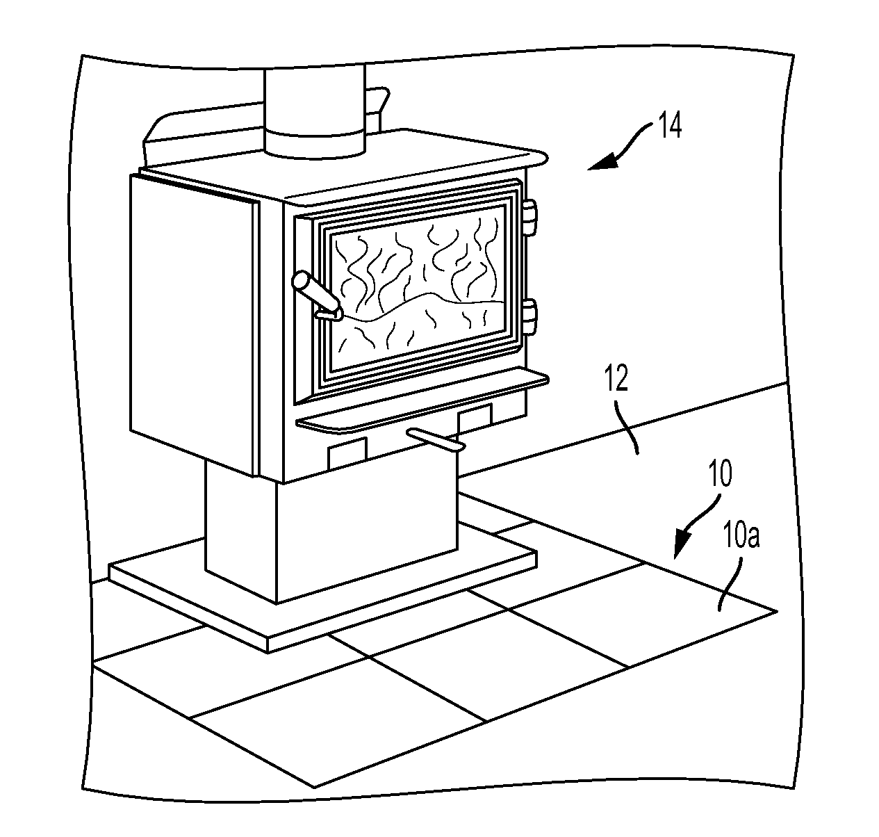
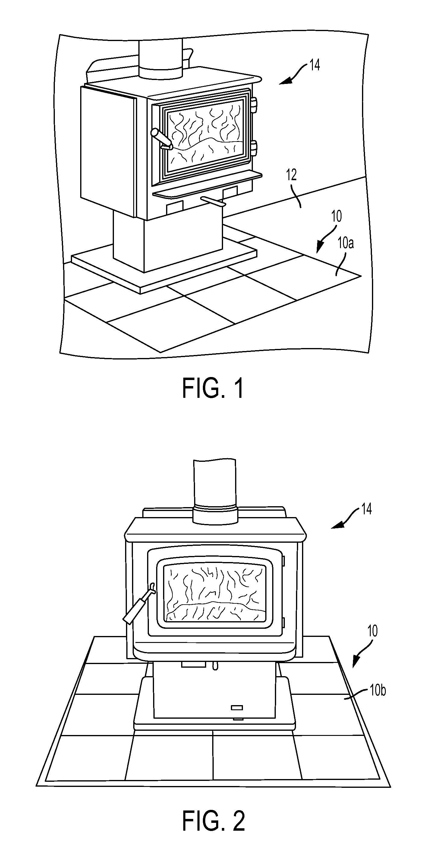
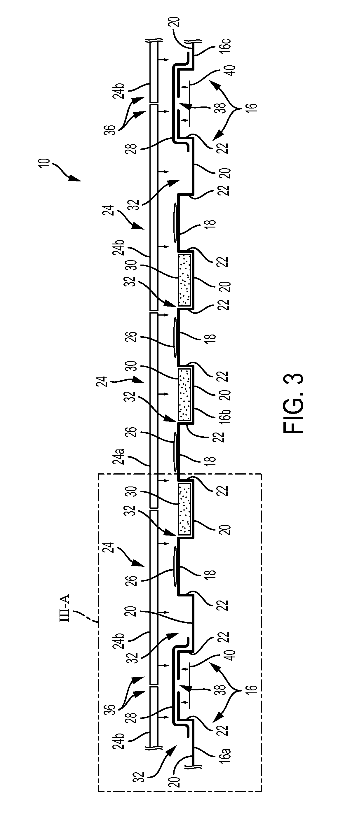
[0030]Referring now to the drawings and the illustrative embodiment depicted therein, a hearth pad assembly 10 is provided for protecting a floor surface 12 in the vicinity of a woodstove 14 or other heat-generating device or appliance, such as shown in FIGS. 1 and 2. Hearth pad assembly 10 may be configured as an unframed hearth pad 10a (FIGS. 1 and 3-4F) or as a framed hearth pad 10b (FIGS. 2 and 5) having additional thermal insulation, as will be described below. Hearth pad assemblies 10 are capable of supporting heavy woodstoves 14 as well as pellet stoves, furnaces, or other heating devices or appliances that require heat-resistant and / or flame or spark-resistant materials in their vicinity, such as for safety and for meeting building codes. However, hearth pad assemblies 10 can be packaged and shipped in a compact and partially broken-down form, as in a kit, and assembled at the installation site. In some embodiments, the hearth pad assembly can be fully assembled an installed...


PUM

PropertyMeasurementUnit
Electrical resistanceaaaaaaaaaa
Shapeaaaaaaaaaa
aaaaaaaaaa

Abstract

A heat-resistant and spark-resistant hearth pad assembly presents a finished appearance along a floor surface, and supports a wood stove or other heat-generating appliance or device. The hearth pad assembly is transportable in compact form as a kit, and is readily assembled at an installation location, preferably without the use of tools. The hearth pad assembly includes first and second formed panels, such as of sheet metal having a corrugated or undulating cross sectional shape including upper surface portions and lower surface portions, with a generally planar overall shape. The formed panels have opposite side edge portions that are placed near one another and coupled together using a securing element during assembly. A plurality of finishing elements, such as tiles, are typically pre-attached to at least the upper surface portions of the formed panels. Optionally, a framework and / or heat-resistant substrate may be respectively positioned around and beneath the formed panels.

Description

CROSS REFERENCE TO RELATED APPLICATION[0001]The present application claims the benefit of U.S. provisional application Ser. No. 61 / 993,741, filed May 15, 2014, which is hereby incorporated herein by reference in its entirety.FIELD OF THE INVENTION[0002]The present invention relates to devices for protecting interior building surfaces, such as flooring, from heat and / or sparks generated by fireplaces, woodstoves, furnaces, and the like.BACKGROUND OF THE INVENTION[0003]Many different heat-resistant and spark-resistant materials and products are available for protecting flooring, wall panels, and other interior building surfaces from heat and / or sparks that may issue from fireplaces, woodstoves, pellet stoves, furnaces, or other appliances. Such heat-resistant and spark-resistant materials and products may include concrete, tile, metals such as steel, stone, sheet materials having thermal insulating properties, and the like, or combinations thereof. In some installations, the materials...

Claims


Application Information

Patent Timeline
IPC IPC(8): F24B1/197B32B37/14B32B37/12F24B1/198
CPCF24B1/197F24B1/198B32B37/14Y10T156/1002B32B2305/72Y10T156/10B32B37/12B32B37/182B32B38/06B32B2307/304B32B2309/10B32B2419/04B32B2607/00F24B13/002
Inventor KREISER, JEFFREY R.YODER, JEFFREY L.
Owner HESTIA INC D B A AMERICAN PANEL HEARTH PROD
Learn More