
Implementation of a magnetic resonance examination at several bed positions in the scanner

a technology of magnetic resonance and scanner, applied in the field of implementing a magnetic resonance whole body examination, can solve problems such as tissue heat, and achieve the effect of easy determination

Active Publication Date: 2015-10-22
SIEMENS HEALTHCARE GMBH
View PDF1 Cites 10 Cited by
  • Summary
  • Abstract
  • Description
  • Claims
  • Application Information

AI Technical Summary

Benefits of technology

The invention provides a method for automatically determining the anatomical structure of a person and the absorption rate of magnetic resonance fields in their tissue. This information is used to create a specific absorption rate for each bed position in the magnetic resonance scanner. The method also includes comparing the absorption rates with a threshold value to alert if they exceed the acceptable range. This way, the measurement parameters of the MRI can be kept constant during the examination, ensuring consistent data collection. Additionally, the method includes a technique for determining the anatomical structure of the person by conducting a magnetic resonance examination at different bed positions, where the examination bed moves continuously or can be stationary. This approach allows for easy identification of the person's position in the MRI system without additional steps or equipment.

Problems solved by technology

The absorption of electromagnetic field energy may result in heating of the tissue and is therefore to be restricted during the implementation of a magnetic resonance examination.
Since the different body regions may have different SAR properties, this may result in the SAR monitor requiring an adjustment of the protocol parameters at individual bed positions, for instance a change in the repetition time TR, the tilt angle or the number of slices.
This can result in the combined image indicating different contrasts, which may be shown as stripes in the image or can no longer be combined on account of reduced slices, since the body of the examination subject is no longer measured in detail.

Method used


Image

  • Implementation of a magnetic resonance examination at several bed positions in the scanner
  • Implementation of a magnetic resonance examination at several bed positions in the scanner
  • Implementation of a magnetic resonance examination at several bed positions in the scanner

Examples


Embodiment Construction

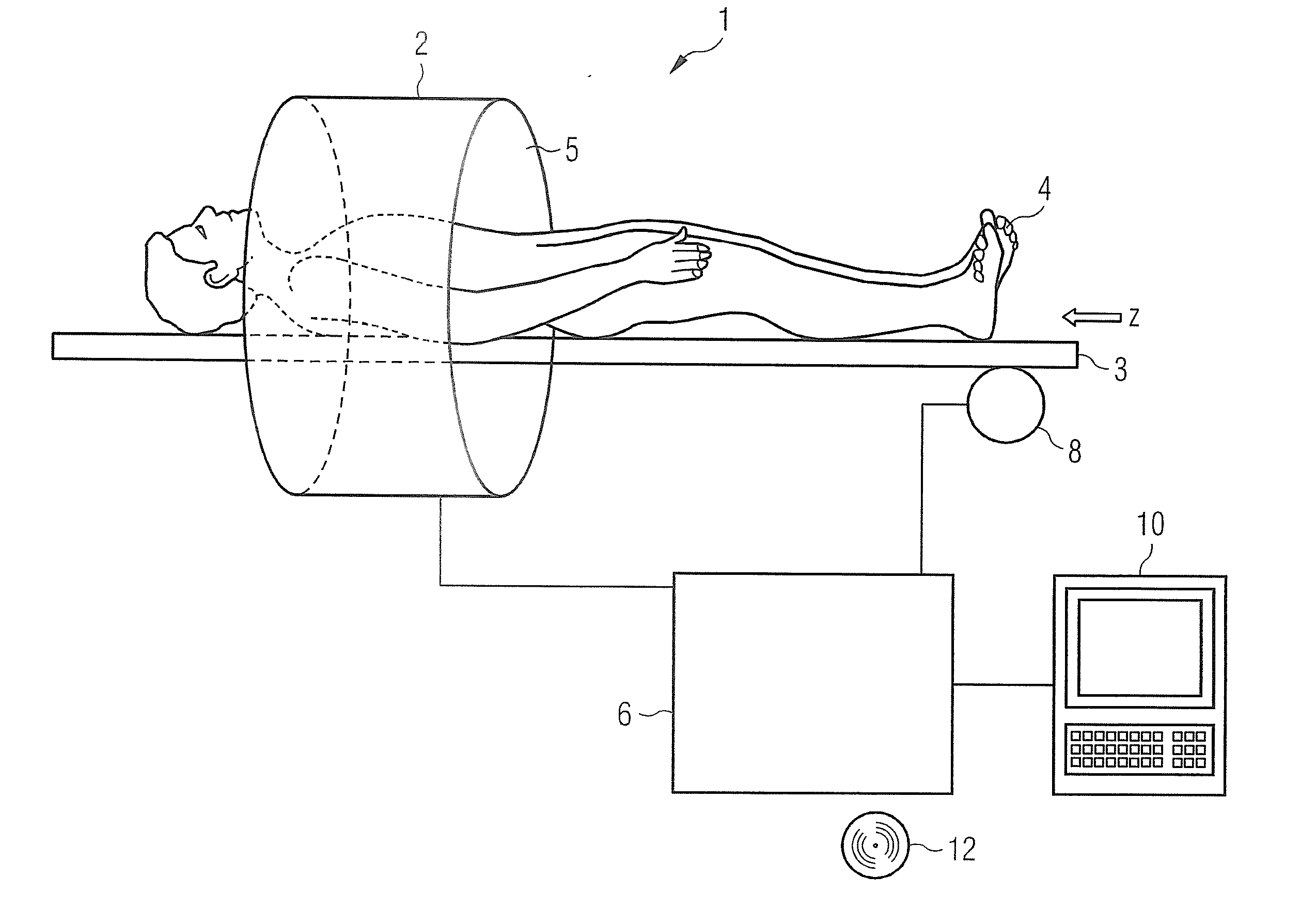
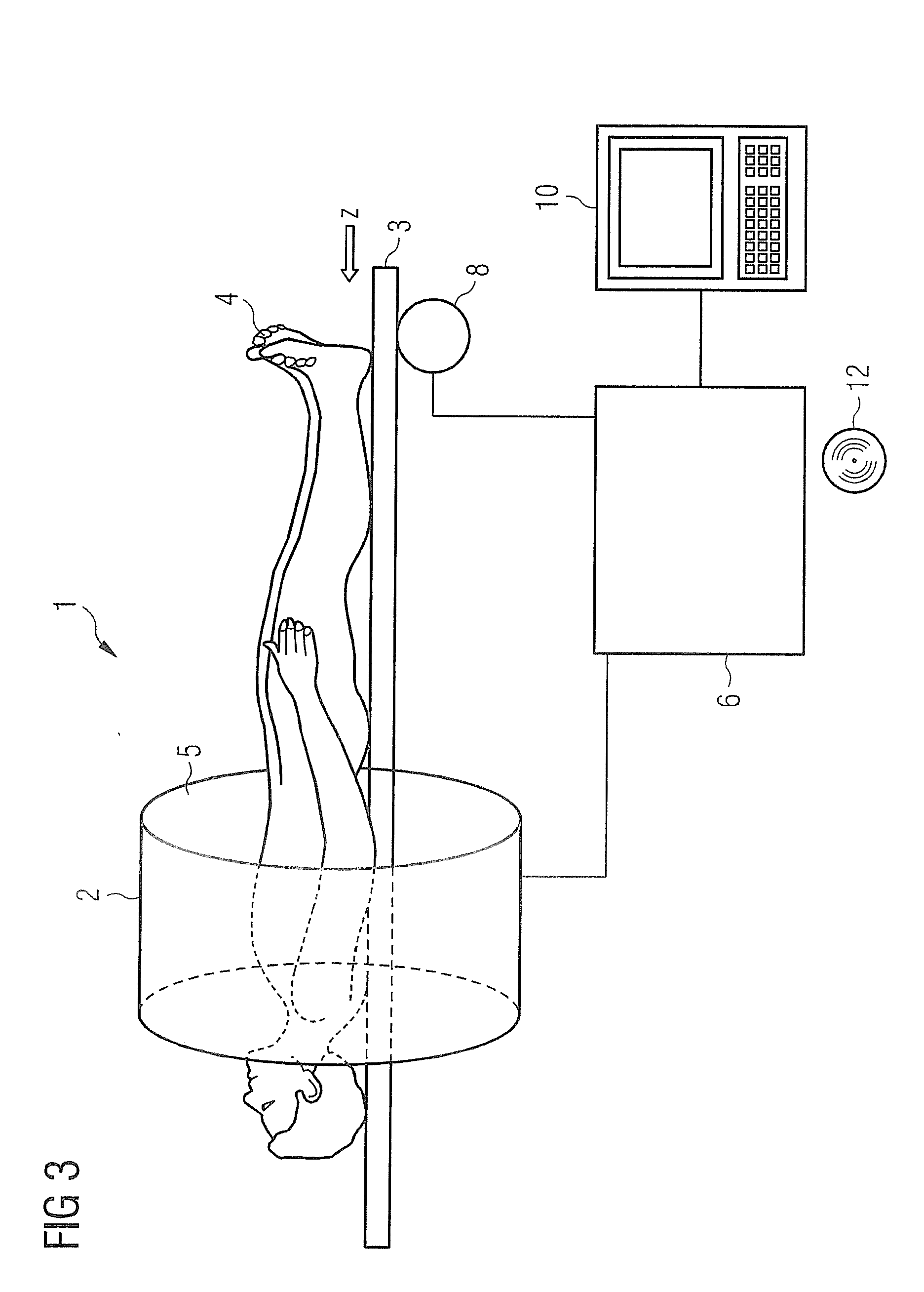
[0028]FIG. 3 is a schematic illustration of a magnetic resonance apparatus 1. The magnetic resonance system 1 includes a scanner (data acquisition unit) 2, an examination bed 3 for an examination subject 4, which can be moved on the examination bed 3 through an opening 5 of the scanner 2, a control computer 6, an evaluation apparatus 7 and a drive unit 8. The control computer 6 actuates the scanner 2 and receives signals from the scanner 2, which are recorded by the scanner 2. In order to generate the magnetic resonance data, the scanner 2 has a basic field magnet (not separately shown), which generates a basic magnetic field B0, and a gradient field system (not separately shown), for generating gradient fields. Furthermore, the scanner 2 includes one or more radio-frequency antennas for generating radio-frequency signals and for receiving measurement signals, which are used by the control computer 6 and the evaluation apparatus 7 for generating magnetic resonance images. The contro...


PUM


Abstract

In a method and magnetic resonance (MR) apparatus for implementing an MR examination of an examination subject with a predetermined MR measurement protocol at several different bed positions of the bed of the MR apparatus, a respective anatomical structure of the examination subject is determined for each of the several bed positions and a respective specific absorption rate is determined for each of the several bed positions as a function of the respective anatomical structure of the examination subject at the corresponding bed position and the predetermined MR measurement protocol. The specific absorption rates for the several bed positions are determined before electromagnetic fields are generated according to the respective predetermined MR measurement protocol. The specific absorption rates are compared with an absorption rate threshold value and a notification is output if at least one of the specific absorption rates exceeds the absorption rate threshold value.

Description

BACKGROUND OF THE INVENTION[0001]1. Field of the Invention[0002]The present invention concerns a method for implementing a magnetic resonance examination of an examination subject in a magnetic resonance system with a predetermined magnetic resonance measurement protocol at several different bed positions of an examination bed of the magnetic resonance system. The present invention relates in particular to magnetic resonance whole-body examinations, such as for screening purposes, which are implemented with different magnetic resonance contrasts or magnetic resonance measurement protocols.[0003]2. Description of the Prior Art[0004]Magnetic resonance examinations can be used in the diagnosis of a multitude of illnesses. Furthermore, magnetic resonance examinations can be used as whole-body examinations for screening purposes, in order to search for sick persons in a defined section of the population within the field of preventative medicine, or to implement various subsequent examina...

Claims


Application Information

Patent Timeline
Patent Type & Authority Applications(United States)
IPC IPC(8): G01R33/483G01R33/56G01R33/563G01R33/30
CPCG01R33/4833G01R33/307G01R33/56341G01R33/5602G01R33/5608
Inventor KEIL, MIRIAM
Owner SIEMENS HEALTHCARE GMBH
Learn More