
High accuracy liquid density sensor

a liquid density sensor, high-accuracy technology, applied in the direction of instruments, specific gravity measurement, measurement devices, etc., can solve the problems of reducing the sensing accuracy, difficult and complicated calculation of nonlinear characteristic curves, etc., and achieve the effect of increasing the sensing accuracy

Active Publication Date: 2015-10-22
FINETEK CO LTD
View PDF0 Cites 3 Cited by
  • Summary
  • Abstract
  • Description
  • Claims
  • Application Information

AI Technical Summary

Benefits of technology

The present invention is a high accuracy liquid density sensor. It works by immersing a sensing rod into the liquid and measuring the distance between two magnetic units at different heights. The sensor can accurately calculate the liquid density based on the distance between the two magnetic units. This results in a more accurate sensing result.

Problems solved by technology

Calculations of nonlinear characteristic curves are very difficult and complicated, that is, the density of the liquid must be calculated through complex calculations, otherwise calculation errors easily occur and decrease accuracy of the sensing result.

Method used


Image

  • High accuracy liquid density sensor
  • High accuracy liquid density sensor
  • High accuracy liquid density sensor

Examples


Embodiment Construction

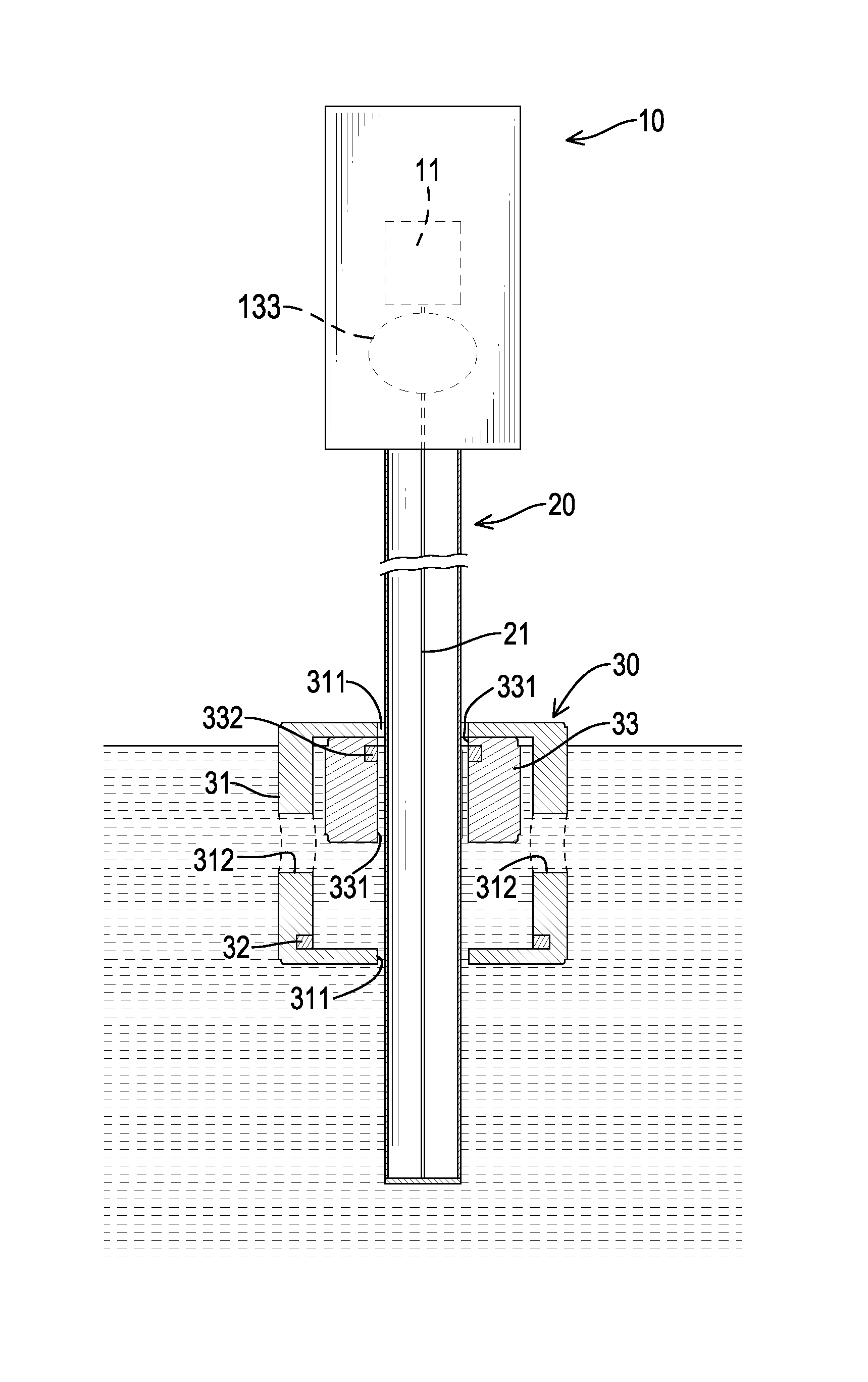
[0035]With reference to FIGS. 1 and 2, a first preferred embodiment of a high accuracy liquid density sensor in accordance with the present invention comprises a sensing module 10, a sensing rod 20 and a floating device 30.

[0036]The sensing module 10 has a control circuit 11 having computing functions.

[0037]The sensing rod 20 comprises a hollow tube and a sensing line 21. One end of the hollow tube is connected to the sensing module 10, and the other end of the hollow tube is to be immersed in liquid. The sensing line 21 is mounted in the sensing rod 20 and electrically connected to the control circuit 11 of the sensing module 10.

[0038]The floating device 30 comprises a housing 31, a first magnetic unit 32 and a floating ball 33.

[0039]The housing 31 has two opposite first openings 311 and two side holes 312, wherein the sensing rod 20 is mounted through the two first openings 311, and the floating device 30 can move along the sensing rod 20. The first magnetic unit 32 is mounted in ...


PUM


Abstract

A liquid density sensor has a sensing module, a sensing rod and a floating device. The sensing module has a control circuit having computing functions. The sensing rod has a sensing line electrically connected to the control circuit. The floating device has a first magnetic unit and a floating ball mounted therein. The sensing rod is mounted through the floating device and the floating ball. The floating ball has a second magnetic unit. A specific gravity of the floating ball is lower than that of the floating device. The control circuit calculates a liquid density of liquid based on a distance between the first magnetic unit and the second magnetic unit according to a linear formula.

Description

BACKGROUND OF THE INVENTION[0001]1. Field of the Invention[0002]The present invention relates to a liquid density sensor, and more particularly to a high accuracy liquid density sensor.[0003]2. Description of Related Art[0004]Generally, a high-pressure liquid storage device usually comprises a liquid density sensor to sense a density of liquid stored in the high-pressure liquid storage device.[0005]With reference to FIG. 8, a conventional liquid density sensor comprises a sensing module, a sensing rod, a first floating ball 70 and a second floating ball 80.[0006]The sensing module 50 has a controller 51 having computing functions.[0007]The sensing rod 60 comprises a hollow tube having two opposite openings and a sensing line 61 mounted in the hollow tube, wherein one end of the sensing line 61 is connected to the controller 51 of the sensing module 50.[0008]The first floating ball 70 has a housing 71, a floating part, a first magnetic unit 73 and a second magnetic unit 74. The housi...

Claims


Application Information

Patent Timeline
IPC IPC(8): G01N9/36
CPCG01N9/36G01N9/12
Inventor CHEN, JIA-YILUO, YUNG-LONGCHEN, WEI-YUCHENG, CHAO-KAI
Owner FINETEK CO LTD
Learn More