
Systems and methods for cold movement detection

a technology of cold movement and detection methods, applied in the direction of railway signalling, railway signalling, vehicle signalling indicators, etc., can solve the problems of low reliability of current systems, etc., to achieve the effect of reducing the number of inspections, replacements, and/or repairs

Active Publication Date: 2015-10-01
GENERAL ELECTRIC CO
View PDF13 Cites 14 Cited by
  • Summary
  • Abstract
  • Description
  • Claims
  • Application Information

AI Technical Summary

Benefits of technology

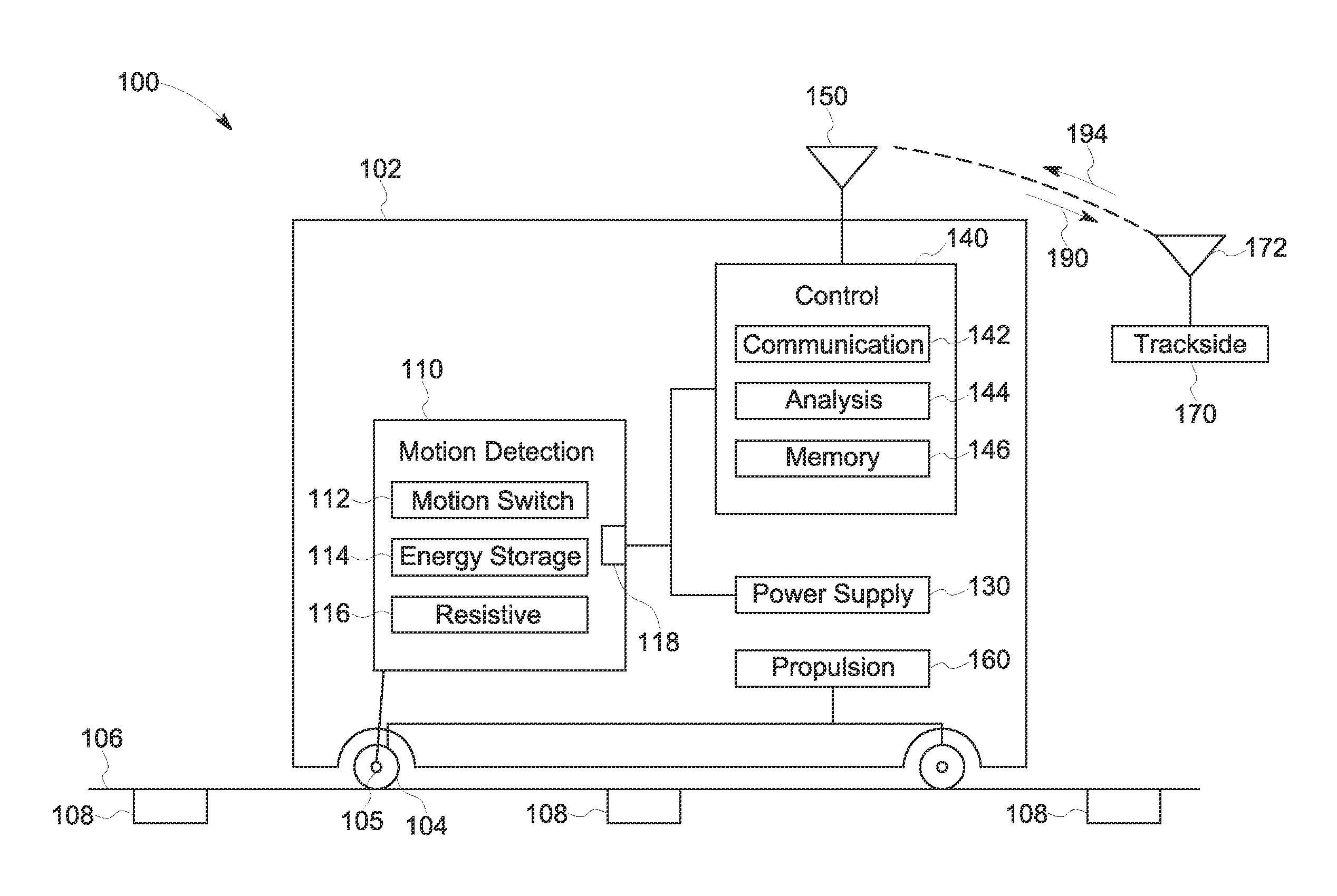
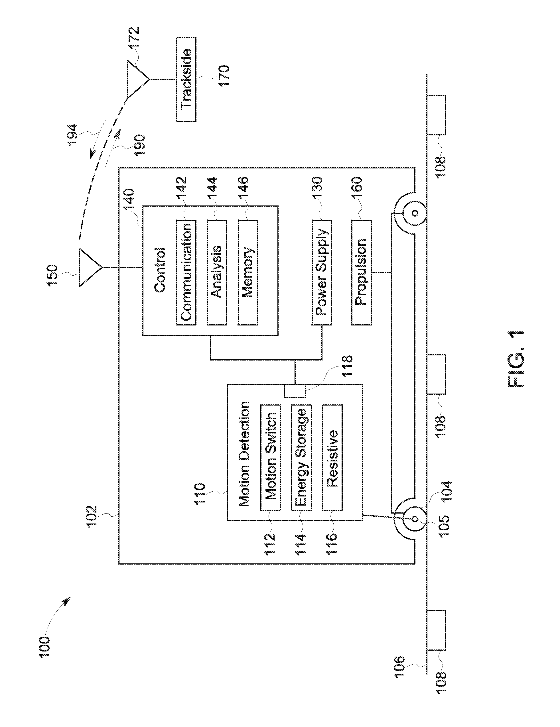
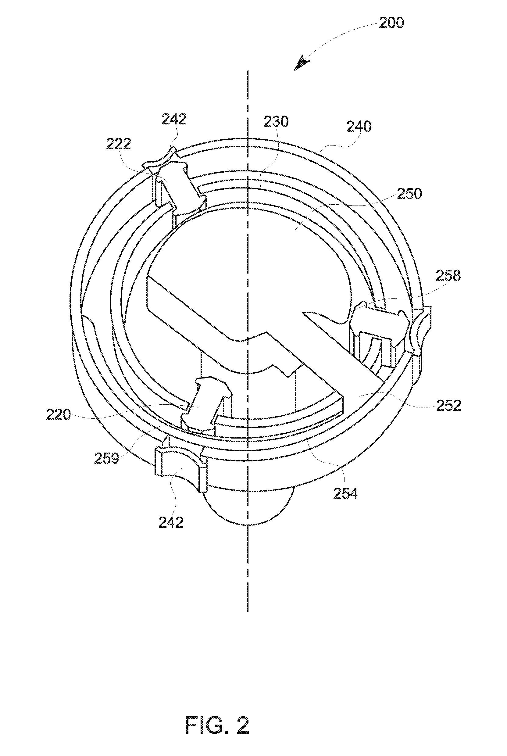
The present inventive subject matter describes a cold movement detection system for a vehicle that includes a motion switch module, an energy storage module, a resistive module, and an interface. The system detects changes in the position of the vehicle through the motion of the axle using the motion switch module and the energy storage module. The energy storage module stores a charge responsive to the motion of the motion activated switch, and the resistive module dissipates the energy stored in the module. The interface provides information about the change in charge state of the energy storage element. The invention is useful for identifying the position of a vehicle that has been powered off and is useful for detecting movement in a vehicle.

Problems solved by technology

If the vehicle is moved during the powered off period (e.g., cold movement), reports of passage over balises will not be provided to the wayside equipment.
Thus, when the vehicle is powered on, although the vehicle has moved, the wayside equipment may not have a report of the movement and may erroneously schedule movements for the vehicle based on the pre-shut down position.
Current cold motion detection systems may use components such as springs that are subject to failure due to vibration of a vehicle system, or magnets which may suffer from interference (e.g., magnetic fields) encountered by vehicle systems, and / or may require an additional power supply.
Current systems thus may suffer from reduced reliability, be subject to relatively fast wear requiring frequent inspection, replacement, and / or repair, and / or suffer from other drawbacks.

Method used


Image

  • Systems and methods for cold movement detection
  • Systems and methods for cold movement detection
  • Systems and methods for cold movement detection

Examples


Embodiment Construction

[0013]The term vehicle consist is used in this document. A vehicle consist can be a group of two or more vehicles that are mechanically coupled to travel together along a route. Optionally, a vehicle consist may have a single propulsion-generating unit or vehicle. The vehicles in a vehicle consist can be propulsion-generating units (e.g., vehicles capable of generating propulsive force, which also are referred to as propulsion-generating units, powered units, or powered vehicles) that may be in succession and connected together so as to provide motoring and / or braking capability for the vehicle consist. The propulsion-generating units may be connected together with or without other vehicles or cars between the propulsion-generating units. One example of a vehicle consist is a locomotive consist that includes locomotives as the propulsion-generating units. Other vehicles may be used instead of or in addition to locomotives to form the vehicle consist. A vehicle consist can also inclu...


PUM


Abstract

A system includes a motion switch module, an energy storage module, a resistive module, and an interface. The motion switch module includes at least one motion activated switch that is movable between an open and a closed position responsive to movement of an axle to which the motion switch module is coupled. The energy storage module includes at least one energy storage element that discharges a stored charge responsive to a motion of the corresponding at least one motion activated switch from the open to the closed position. The resistive module includes least one resistive element that dissipates energy discharged by the corresponding at least one energy storage module. The interface is configured to provide information regarding a change in charge state of the at least one energy storage element, wherein the change in charge state corresponds to a movement of the vehicle.

Description

RELATED APPLICATIONS[0001]This application claims priority to U.S. Provisional Application No. 61 / 973,522, which was filed on 1 Apr. 2014, and is entitled “SYSTEMS AND METHODS FOR COLD MOVEMENT DETECTION” (the “'522 Application”). The entire disclosure of the '522 Application is incorporated by reference herein in its entirety.BACKGROUND[0002]Wayside equipment in a transportation network may be used to schedule and control the activities of one or more vehicles traversing a route (or routes) of the transportation network. However, to prevent conflicts between vehicles on the same route, or to avoid travel over sections of the route that are in need of repair or otherwise not in condition for passage of vehicles, the wayside equipment must have an accurate understanding of the position of each vehicle in the transportation network. For example, as the vehicles travel in the network, the vehicles may pass over balises, with information describing which vehicles passed over which balis...

Claims


Application Information

Patent Timeline
Patent Type & Authority Applications(United States)
IPC IPC(8): B61L25/02B61L15/00B61L13/00
CPCB61L25/02B61L15/0018B61L13/002B61L25/021
Inventor LOZANO, FRANCISCOMALESCI, ANDREAPAPINI, MARIO
Owner GENERAL ELECTRIC CO
Learn More