
Safety Rail

a safety rail and rail technology, applied in the field of safety rail, can solve the problems of increasing transportation cost and increasing manufacture cost, and achieve the effect of reducing replacement cost and lowering manufacture cos

Inactive Publication Date: 2015-09-17
CHANG SHIH KUO
View PDF10 Cites 11 Cited by
  • Summary
  • Abstract
  • Description
  • Claims
  • Application Information

AI Technical Summary

Benefits of technology

The present invention aims to provide a safety rail that allows for easy replacement of components, reducing replacement costs. Additionally, some components can be made of metal material, while others can be made of plastic material, reducing manufacture costs.

Problems solved by technology

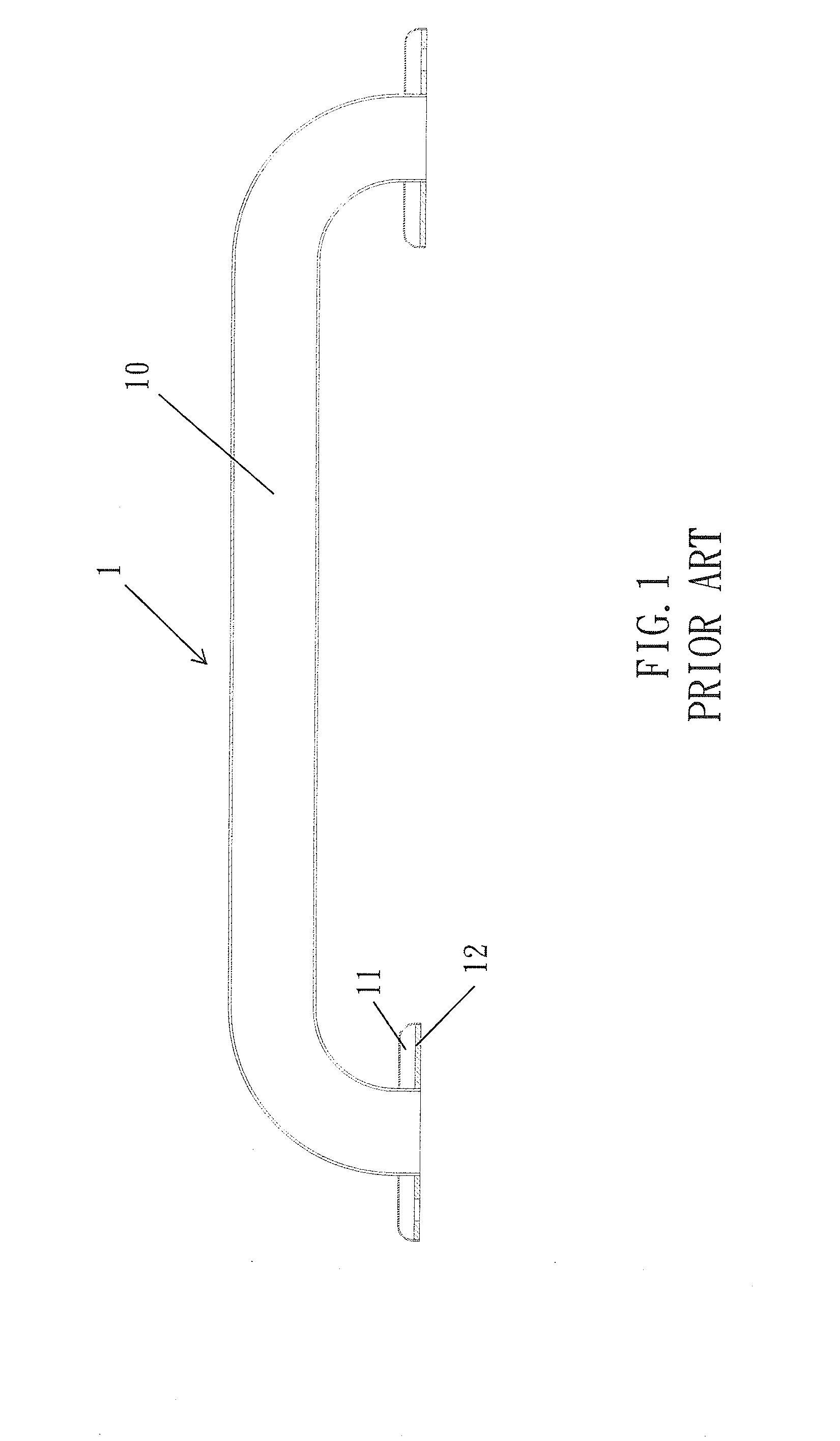
1. The conventional safety rail 1 is one piece made to have a large size, thus increasing transportation cost.
2. The conventional safety rail 1 is one piece made of the metal material, thereby increasing manufacture cost.

Method used


Image

  • Safety Rail
  • Safety Rail
  • Safety Rail

Examples


first embodiment

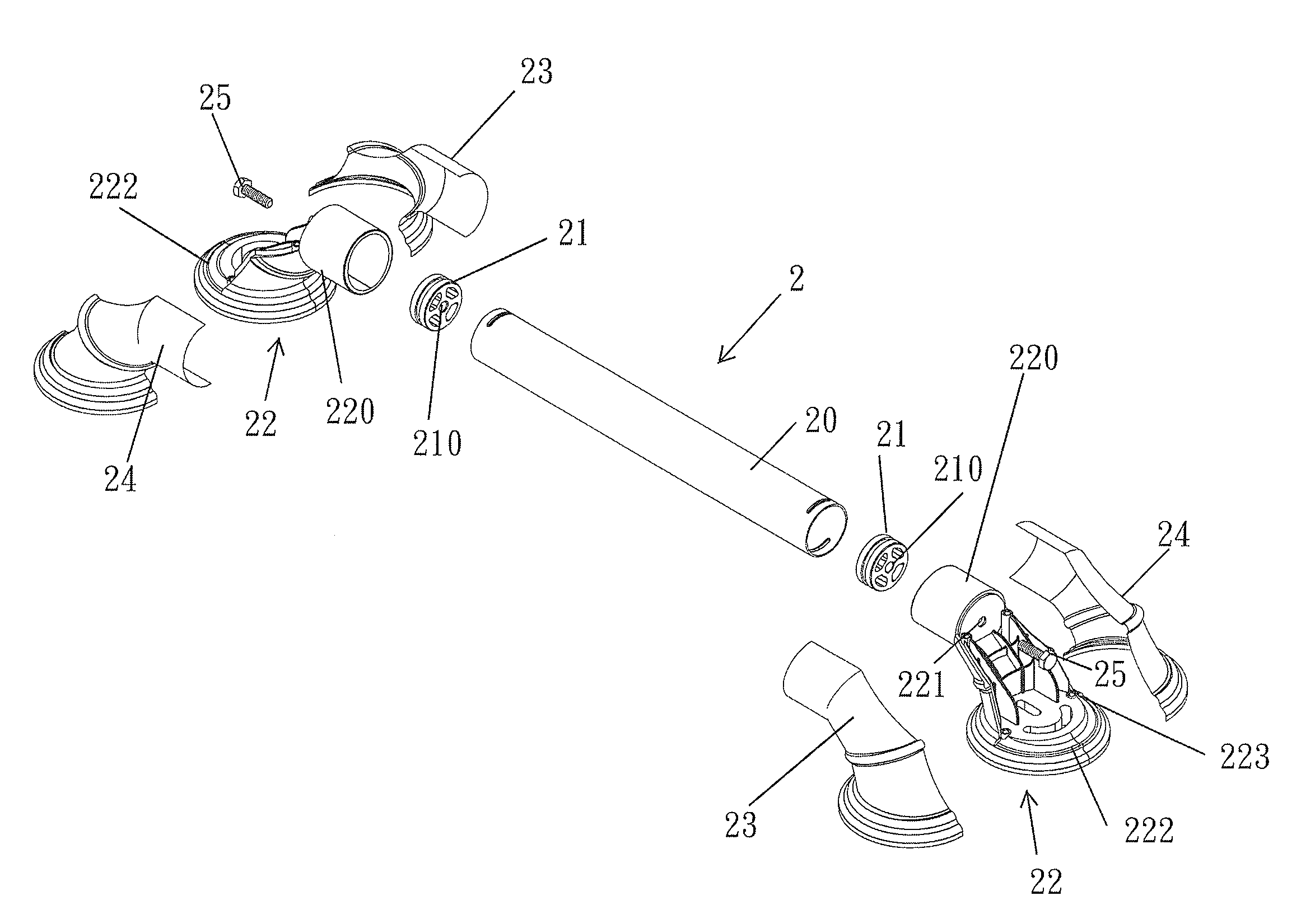
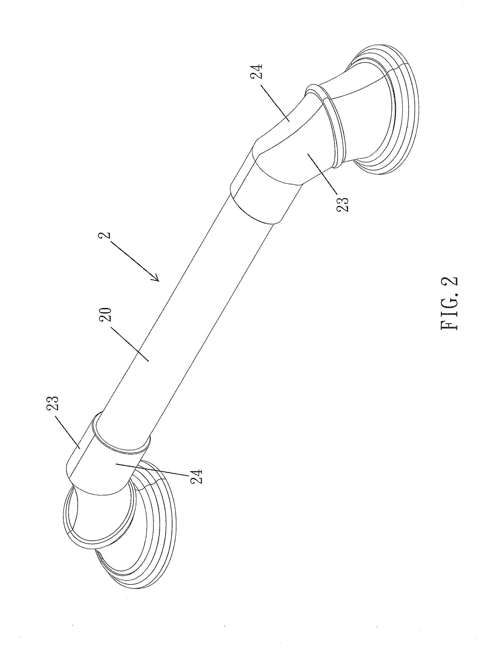
[0016]With reference to FIGS. 2-4, a safety rail 2 according to the present invention comprises: a tube 20, two connecters 21, two fixing holders 22, two first covers 23, two second covers 24, and two screwing elements 25. Each connector 21 includes an orifice 210 defined on a central position thereof so as to screw with each of the two screwing elements 25. Each fixing holder 22 is one piece formed and includes a fitting member 220 disposed on a first end thereof so as to fit with the tube 20, the fitting member 220 has a hole 221 formed on a central position thereof so as to insert each of the two screwing elements 25, each fixing holder 22 also includes a circular disc 222 mounted on a second end thereof so as to couple with a wall surface and an aperture 223 arranged on a predetermined position thereof. Each first cover 23 and each cover 24 are employed to cover each fixing holder 22. In assembly, the two connecters 21 are connected on two ends of the tube 20, the two fixing hol...

second embodiment

[0017]As shown in FIGS. 5-7, each of two casings 26 of the present invention is applied to replace a respective one of the two first covers 23 and a respective one of the two second covers 24 so that each casing 26 is covered on each fixing holder 22 after each fixing holder 22 and the tube 20 are coupled together, thus assembling the safety rail 2.


PUM


Abstract

A safety rail contains: a tube, two connecters, two fixing holders, two first covers, two second covers, and two screwing elements. Each connector includes an orifice defined on a central position thereof so as to screw with each of the two screwing elements. Each fixing holder includes a fitting member disposed on a first end thereof so as to fit with the tube, the fitting member has a hole formed on a central position thereof so as to insert each of the two screwing elements, each fixing holder also includes a circular disc mounted on a second end thereof so as to couple with a wall surface and an aperture arranged on a predetermined position thereof. Each first cover and each cover are employed to cover each fixing holder.

Description

FIELD OF THE INVENTION[0001]The present invention relates to a safety rail in which any component can be replaced independently so as to reduce replacement cost.BACKGROUND OF THE INVENTION[0002]As shown in FIG. 1, a conventional safety rail 1 contains a tube 10 and two covers 11, wherein the tube 10 is one piece made of metal material and includes two fixing members 12 disposed on two ends thereof so as to connect with a wall surface, such that the tube 10 is connected with the wall surface by inserting two screws through the two fixing members 12 and screwing the two screws with the wall surface, and then the two covers 11 are covered onto the two fixing members 12. However, the conventional safety rail 1 has disadvantages as follows:[0003]1. The conventional safety rail 1 is one piece made to have a large size, thus increasing transportation cost.[0004]2. The conventional safety rail 1 is one piece made of the metal material, thereby increasing manufacture cost.[0005]3. When one o...

Claims


Application Information

Patent Timeline
Patent Type & Authority Applications(United States)
IPC IPC(8): E04F11/18
CPCE04F11/1836E04F11/1804E04F2011/1885E04F2011/1868E04F11/1808E04F2011/1889E04F2011/1897
Inventor CHANG, SHIH-KUO
Owner CHANG SHIH KUO
Learn More