
DC power transmission systems and method of assembling the same

a technology of dc power transmission and load, which is applied in the direction of power conversion systems, electric power transfer ac networks, electrical equipment, etc., can solve the problems of increased operator costs, reactive losses of ac transmission systems, and compounded reactive losses

Active Publication Date: 2015-09-03
GENERAL ELECTRIC CO
View PDF4 Cites 6 Cited by
  • Summary
  • Abstract
  • Description
  • Claims
  • Application Information

AI Technical Summary

Benefits of technology

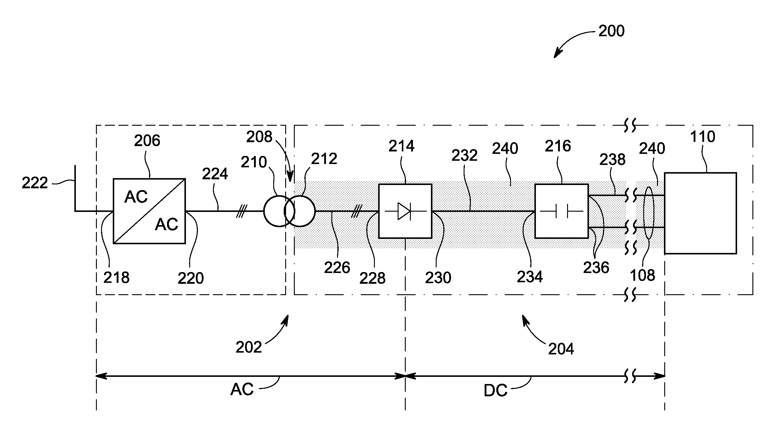
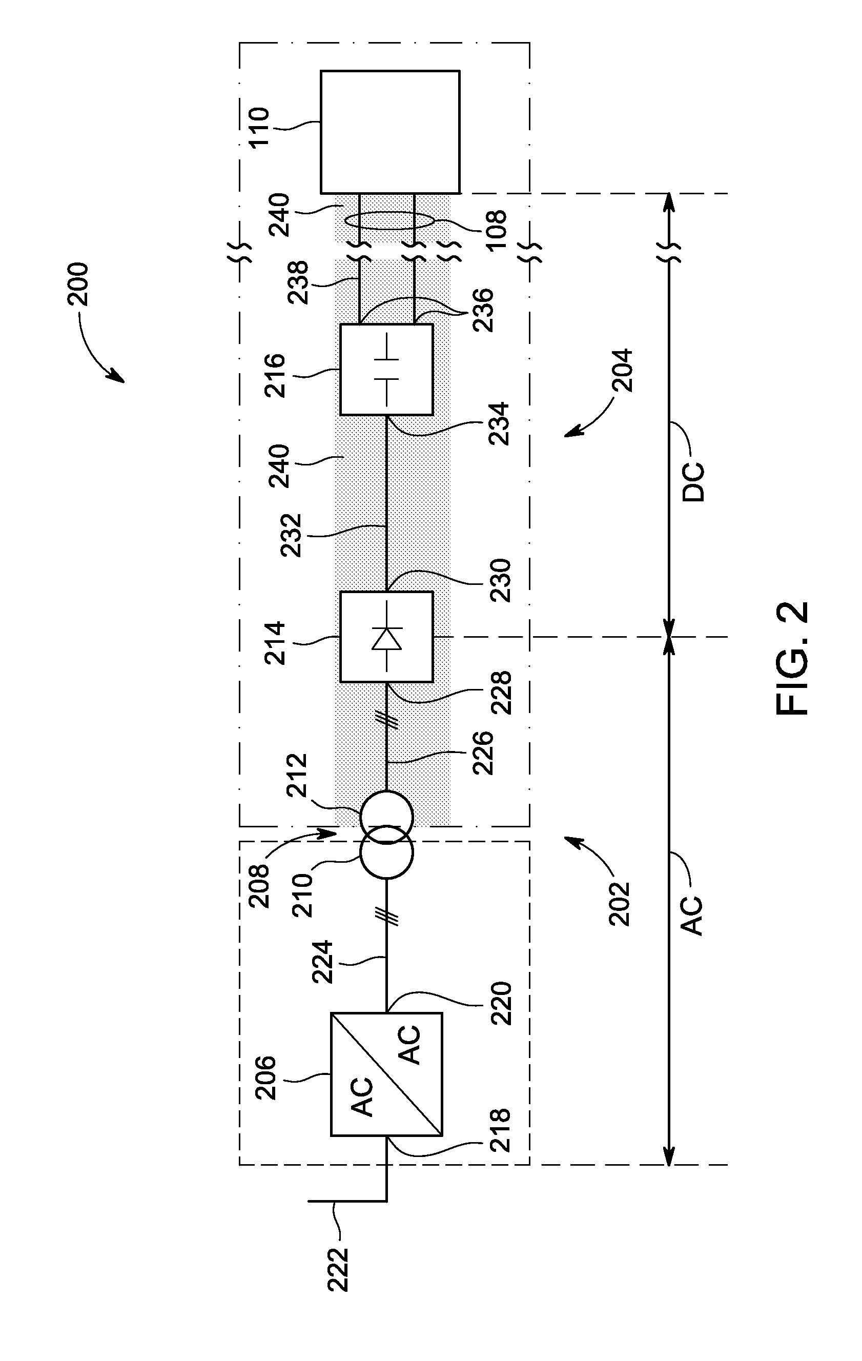
This patent describes a system for transmitting DC power using a transformer with both variable and constant components. The system includes an AC stage with an AC / AC converter and a primary winding, and a secondary winding that is coupled to the AC / AC converter through the primary winding. The system also includes an AC / DC conversion stage with an AC / DC rectifier that converts AC power to DC power without external control. The generated electric field is used to generate an electrical field that includes a substantially constant component and a varying component. The system can efficiently convert AC power to DC power and provide a stable output. The method of assembly involves connecting the AC / AC converter to the primary winding without insulating features, and then connecting the secondary winding to the AC / DC rectifier. The technical effects of this patent are a more reliable and stable power transmission system with improved efficiency and control over the output voltage.

Problems solved by technology

However, AC transmission systems have reactive losses associated with the transmission cables that do not exist in DC transmission systems.
This is especially true in undersea cables, where the reactive losses are compounded.
However, known DC transmission systems have some inefficiencies that cause increased costs for operators.
Accordingly, the size, amount of materials, and cost of the active components with DC insulation to ground can be significant.
As some applications of DC power transmission systems have limited free space, for example, oil and gas platforms, current DC power transmission systems may be too large for a single platform, significantly increasing capital investment and operational costs.

Method used


Image

  • DC power transmission systems and method of assembling the same
  • DC power transmission systems and method of assembling the same
  • DC power transmission systems and method of assembling the same

Examples


Embodiment Construction

[0019]In the following specification and the claims, reference will be made to a number of terms, which shall be defined to have the following meanings.

[0020]The singular forms “a”, “an”, and “the” include plural references unless the context clearly dictates otherwise.

[0021]“Optional” or “optionally” means that the subsequently described event or circumstance may or may not occur, and that the description includes instances where the event occurs and instances where it does not.

[0022]Approximating language, as used herein throughout the specification and claims, may be applied to modify any quantitative representation that could permissibly vary without resulting in a change in the basic function to which it is related. Accordingly, a value modified by a term or terms, such as “about” and “substantially”, are not to be limited to the precise value specified. In at least some instances, the approximating language may correspond to the precision of an instrument for measuring the val...


PUM


Abstract

A DC power transmission system is configured to generate an electric field including components substantially constant with respect to time and varying with time. The DC power transmission system includes an AC stage configured to receive AC electrical power. The AC stage includes a transformer including primary windings and secondary windings configured to be electromagnetically coupled to, and electrically isolated from, each other. The AC stage also includes an AC / AC converter having substantially no insulating features against the at least one substantially constant component of the electric field. The AC / AC converter is electrically coupled to the primary windings. The DC power transmission system also includes an AC / DC conversion stage positioned downstream of the AC stage. The AC / DC conversion stage includes an AC / DC rectifier configured to convert AC electrical power to DC electrical power without external control. The AC / DC rectifier is coupled to the secondary windings.

Description

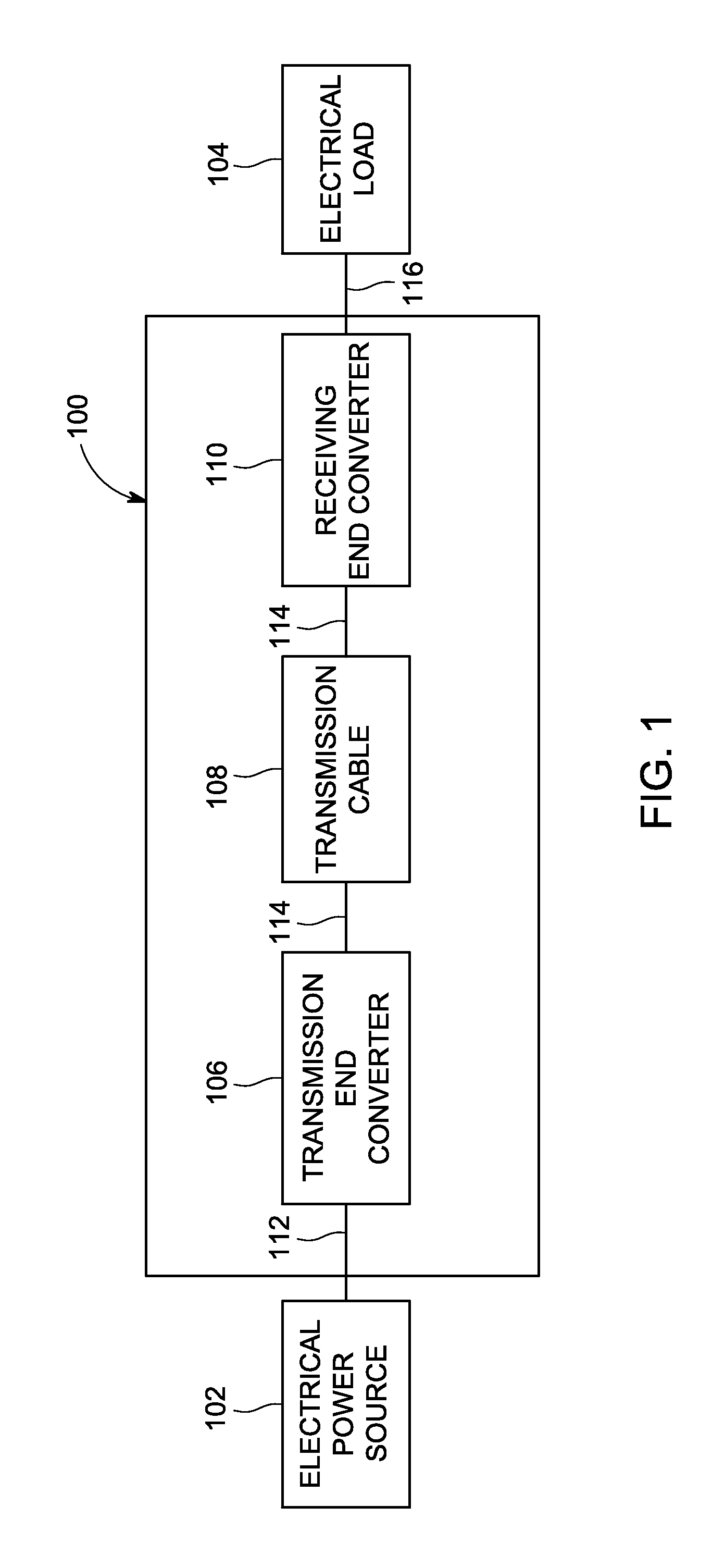
BACKGROUND[0001]The field of the disclosure relates generally to systems and methods for transmitting direct current (DC) power to a load, and more specifically to a DC transmission system having a converter with an active alternating current (AC) stage that does not require heavy DC insulation with respect to ground and a passive AC-to-DC conversion stage.[0002]Most land based transmission systems transmit AC power from an electrical power source, such as a generator, to an electrical load, such as a motor. Any conversion to DC power is typically performed as close to the electrical load as possible. AC power transmission systems are more prevalent than DC transmission systems due to the reduced cost and improved efficiency of AC transformers and switch gear. However, AC transmission systems have reactive losses associated with the transmission cables that do not exist in DC transmission systems. Accordingly, DC transmission systems may be more efficient and cost effective when tra...

Claims


Application Information

Patent Timeline
Patent Type & Authority Applications(United States)
IPC IPC(8): H02M7/06H02M1/12H02M5/04H02M1/14
CPCH02M7/06H02M5/04H02M1/12H02M1/14H02J3/36H02M7/48Y02E60/60
Inventor WIJEKOON, PINIWAN THIWANKA BANDARASIHLER, CHRISTOF MARTINSCHROEDER, STEFANSHEN, JIETENCA, PIERLUIGI
Owner GENERAL ELECTRIC CO
Learn More