
E-cigarette personal vaporizer

a vapourizer and electronic technology, applied in the direction of tobacco, instruments, packaged goods, etc., can solve the problems of insufficient recharging of pvs, insufficient cigalites, and ineffective e-liquid pvs, so as to reduce consumption, reduce consumption, and be easily and quickly replaced by users

Active Publication Date: 2015-09-03
AYR LTD
View PDF9 Cites 71 Cited by
  • Summary
  • Abstract
  • Description
  • Claims
  • Application Information

AI Technical Summary

Benefits of technology

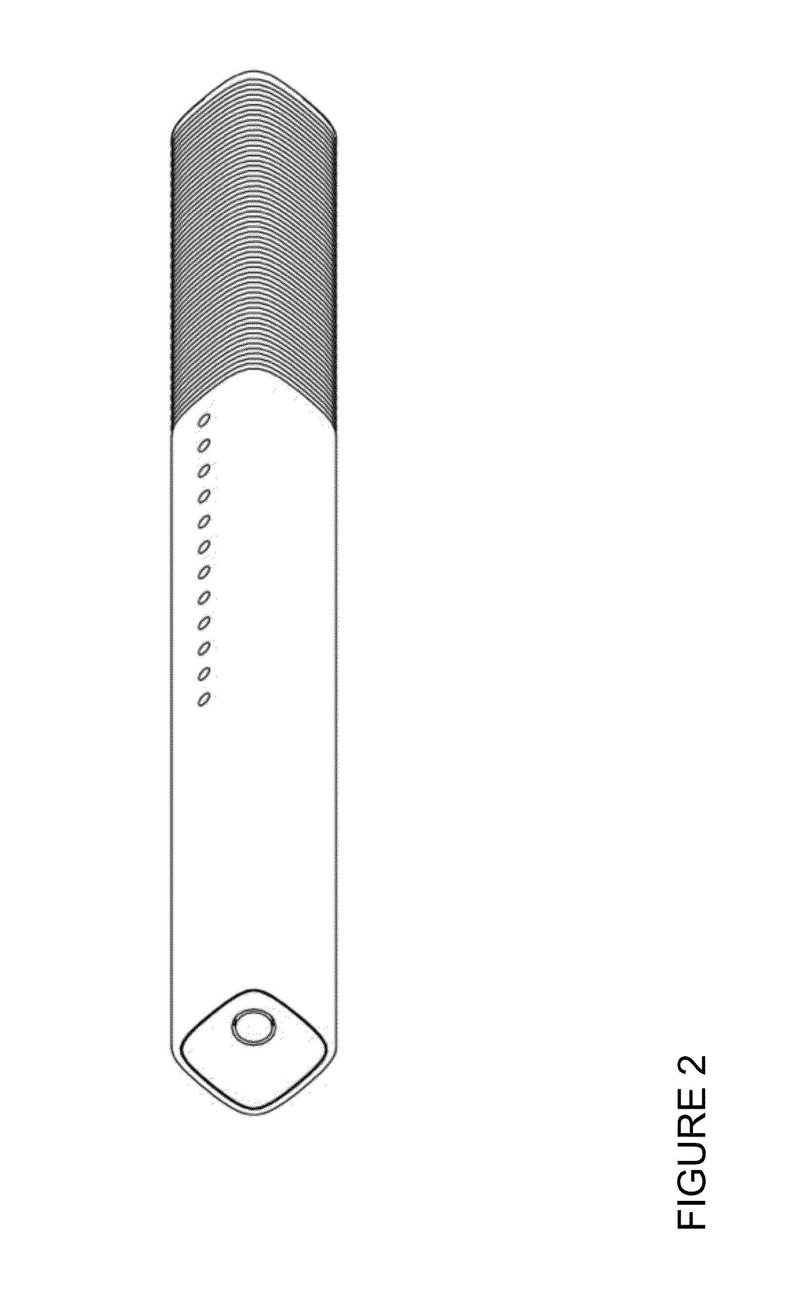
The invention is a re-fillable and re-chargeable e-cigarette PV that has a visual indicator that moves along its body to show when the e-liquid is being used up. This is helpful for users who want to know when they need to refill the e-cigarette.

Problems solved by technology

Specifically, an effective e-liquid PV consumes a significant amount of e-liquid and also current.
Cigalites have not sold well in the market because they permit neither high e-liquid consumption nor high current.
Cases that can merely re-charge a PV are not good enough because the PVs need to be frequently re-filled with e-liquid, which means dis-assembling them, which is messy and inconvenient.
This high consumption would, with a conventional PV design be highly inconvenient because of the need to disassemble the PV and manually drip e-liquid into a small reservoir by squeezing a bottle of e-liquid.
It would be possible also to include power control buttons, dials etc on the Case 100 itself, although this would add to complexity and cost.
There may some residue of the previous flavour in the pump, possibly affecting the vaping experience.
A significant problem with conventional e-cigarette PV designs is that re-filling a cartridge reservoir is slow and can be messy; it typically requires the user to purchase small bottles of e-liquid and to carefully dis-assemble the PV and then re-fill the cartridge by lining up the nozzle of a bottle and squeezing gently.
Equally, removing a spent, non-refillable cartridge and replacing it with a new cartridge, whilst not messy, is wasteful, especially as typical cartridges are not recyclable.
This kind of indicator is very useful because if the user tries to inhale before the atomizer is effectively able to create a vapour with the correct characteristics (which happens if the e-liquid is too cool and viscous), then the user experience is very poor.
In conventional PVs with a small rechargeable battery, time can generally not be used as a proxy because users do not reliably keep the battery close to fully charged.
Absorption materials should not absorb moisture in vapour suspension as this would harm inhalation, only liquids that are free moving in the vapouriser case are absorbed.
It is highly unlikely that the wick will itself permit the migration of droplets of e-liquid that could then leak out from the mouthpiece.

Method used


Image

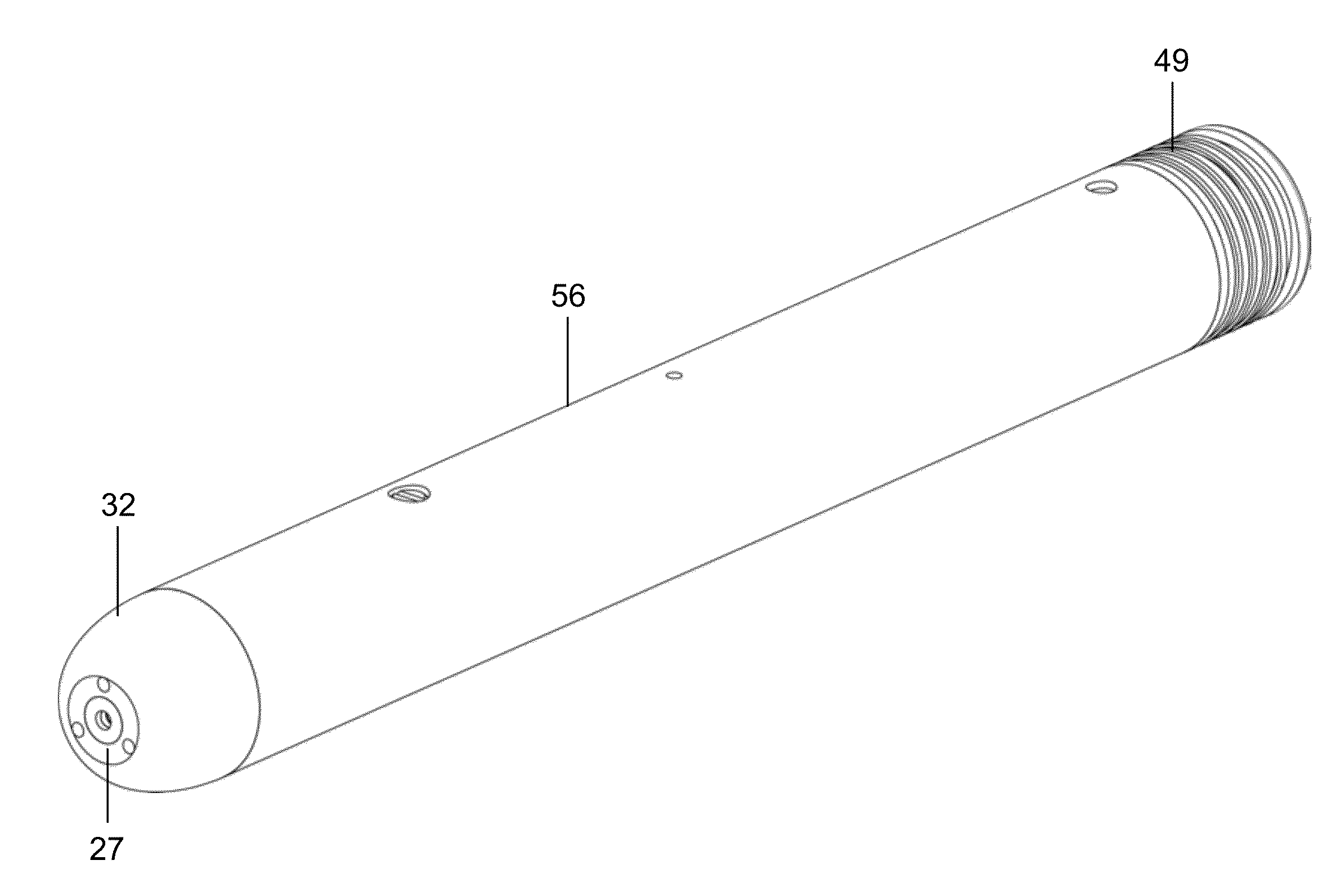
  • E-cigarette personal vaporizer
  • E-cigarette personal vaporizer
  • E-cigarette personal vaporizer

Examples


Embodiment Construction

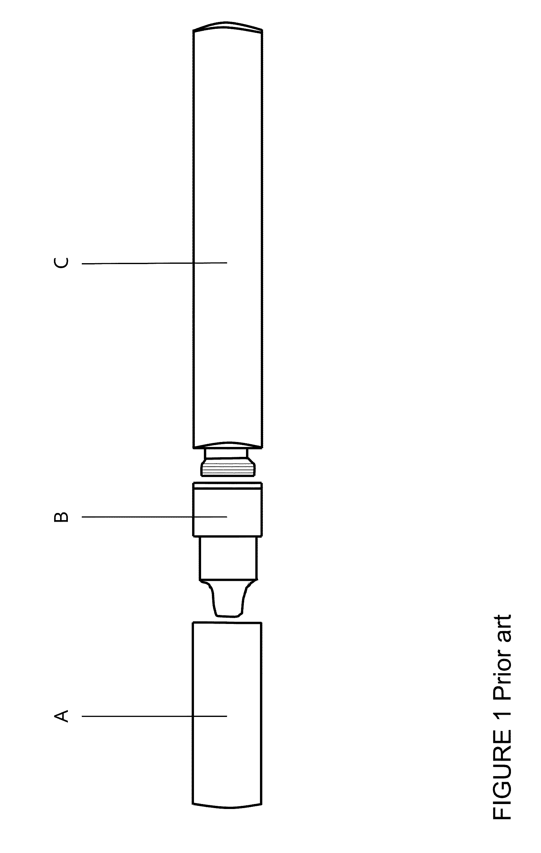
[0221]FIG. 1 shows a conventional personal vapouriser (‘PV’). The PV includes the following key components: a ‘juice’ or ‘e-liquid’ delivery and container system, called a cartridge (A), and an atomizer (B) for vapourising the juice, and a power source (C) to power the atomiser. The cartridge also forms the mouthpiece. A typical design, as shown in FIG. 1, requires the battery (C) to be screwed into the atomiser (B), and the cartridge (A) is then pushed onto the free end of the atomiser B. When the cartridge is fully consumed, the user discards the used cartridge and replaces it with a new one. An alternative design sees the cartridge as user-refillable, typically from a small bottle of e-liquid.

[0222]Conventional PV designs suffer a number of drawbacks. This Detailed Description section describes a number of high-level features which address the most significant drawbacks. An implementation of this invention uses one or more of these high level features.

[0223]We will organise our d...


PUM


Abstract

A re-fillable and re-chargeable e-cigarette PV in which the PV indicates consumption of e-liquid using a visual indicator that extends or moves along the body.

Description

CROSS-REFERENCE TO RELATED APPLICATIONS[0001]This application is based on and claims priority to UK Application No. 1403566.1, filed Feb. 28, 2014; UK Application No. 1408173.1, filed May 8, 2014; UK Application No. 1413028.0, filed Jul. 25, 2014; UK Application No. 1413030.6, filed Jul. 25, 2014; U.S. Provisional Application No. 62 / 045,680, filed Sep. 4, 2014; and U.S. Provisional Application No. 62 / 045,688, filed Sep. 4, 2014, the entire contents of each of which being fully incorporated herein by reference.BACKGROUND OF THE INVENTION[0002]1. Field of the Invention[0003]The field of the invention relates to an electronic cigarette personal vapouriser, also known as an electronic cigarette (e-cig or e-cigarette), vapestick, modding kit, personal vaporizer (PV), advanced personal vaporizer (APVs) or electronic nicotine delivery system (ENDS). In this specification, we will typically use TV′ or ‘e-cigarette’ as the generic term. A PV vapourises ‘e-liquid’ or vaping substance to produ...

Claims


Application Information

Patent Timeline
Patent Type & Authority Applications(United States)
IPC IPC(8): A24F47/00A24F15/12
CPCA24F15/12A24F47/008A24F40/60A24F40/10A24F40/95A24F15/015H02J7/0063A61M2209/045A61M15/06B65D85/10H02J7/0044H02J7/0045A24F15/005A24B15/167B65B3/04B65D25/005G01F23/00G09F2023/0025A24F40/42A24F40/485A24F40/90A24F40/465H01M10/00A24F40/53A24F40/65H05B6/36G06Q30/06H01M2220/30Y02E60/10H02J50/10H02J7/00H02J7/35A24F40/40A24F40/50A24F40/48B65B37/06H02J7/0042
Inventor MEMARI, KAVEHBENNETT, ADRIANMURISON, IANMARSH, STEPHEN
Owner AYR LTD
Learn More