Integrated slack adjuster with improved environmental protection

a technology of environmental protection and slack adjuster, which is applied in the field of slack adjusters, can solve the problems of environmental damage and prior art slack adjusters

Inactive Publication Date: 2015-08-20
NEW YORK AIR BRAKE CORP
View PDF11 Cites 6 Cited by
  • Summary
  • Abstract
  • Description
  • Claims
  • Application Information

AI Technical Summary

Problems solved by technology

However, prior art slack adjusters suffer from the disadvantage that the

Method used


Image

  • Integrated slack adjuster with improved environmental protection
  • Integrated slack adjuster with improved environmental protection
  • Integrated slack adjuster with improved environmental protection

Examples


Embodiment Construction

[0025]Exemplary embodiments are discussed in detail below. While specific exemplary embodiments are discussed, it should be understood that this is done for illustration purposes only. In describing and illustrating the exemplary embodiments, specific terminology is employed for the sake of clarity. However, the embodiments are not intended to be limited to the specific terminology so selected. Persons of ordinary skill in the relevant art will recognize that other components and configurations may be used without departing from the true spirit and scope of the embodiments. It is to be understood that each specific element includes all technical equivalents that operate in a similar manner to accomplish a similar purpose. The examples and embodiments described herein are non-limiting examples.

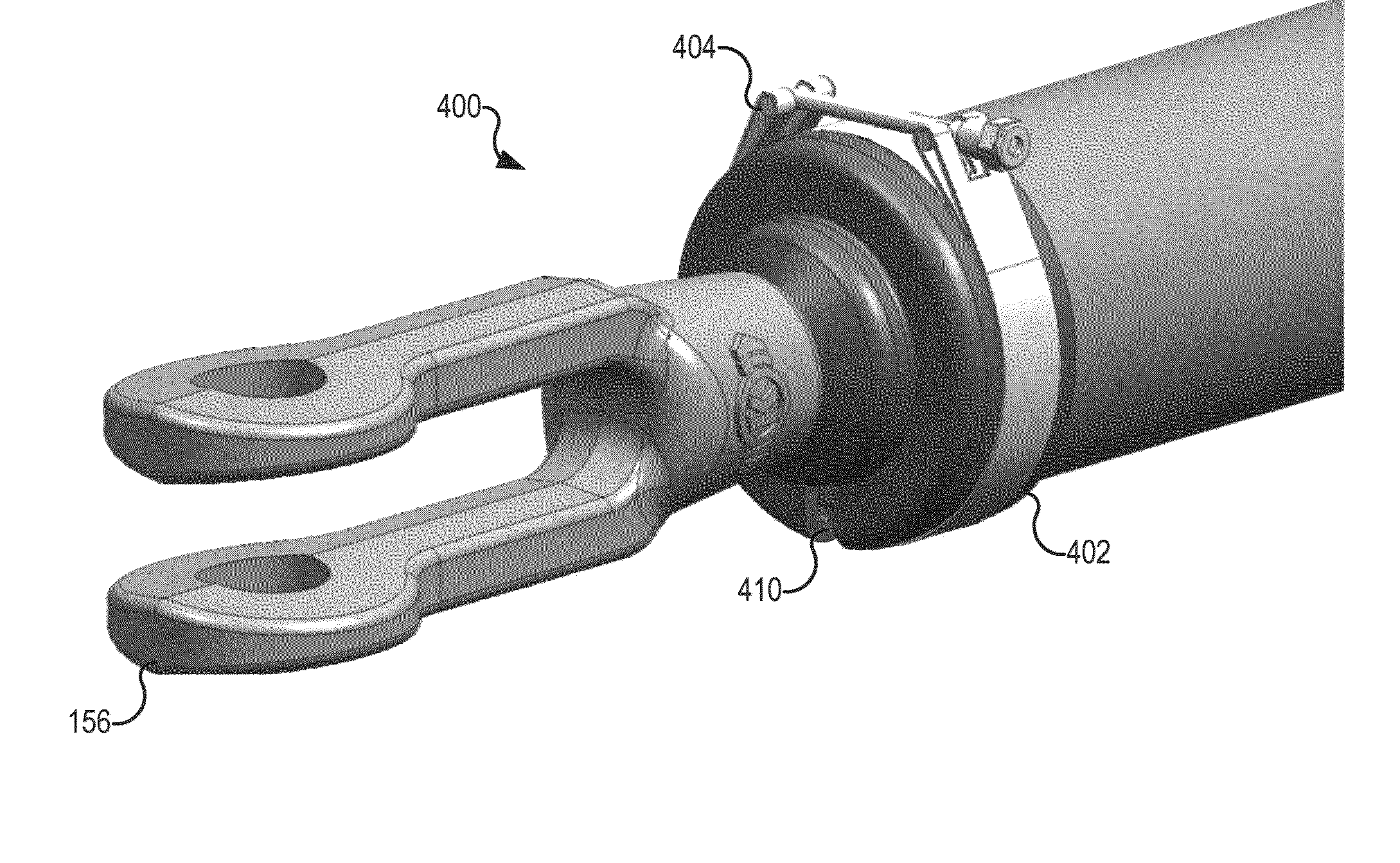
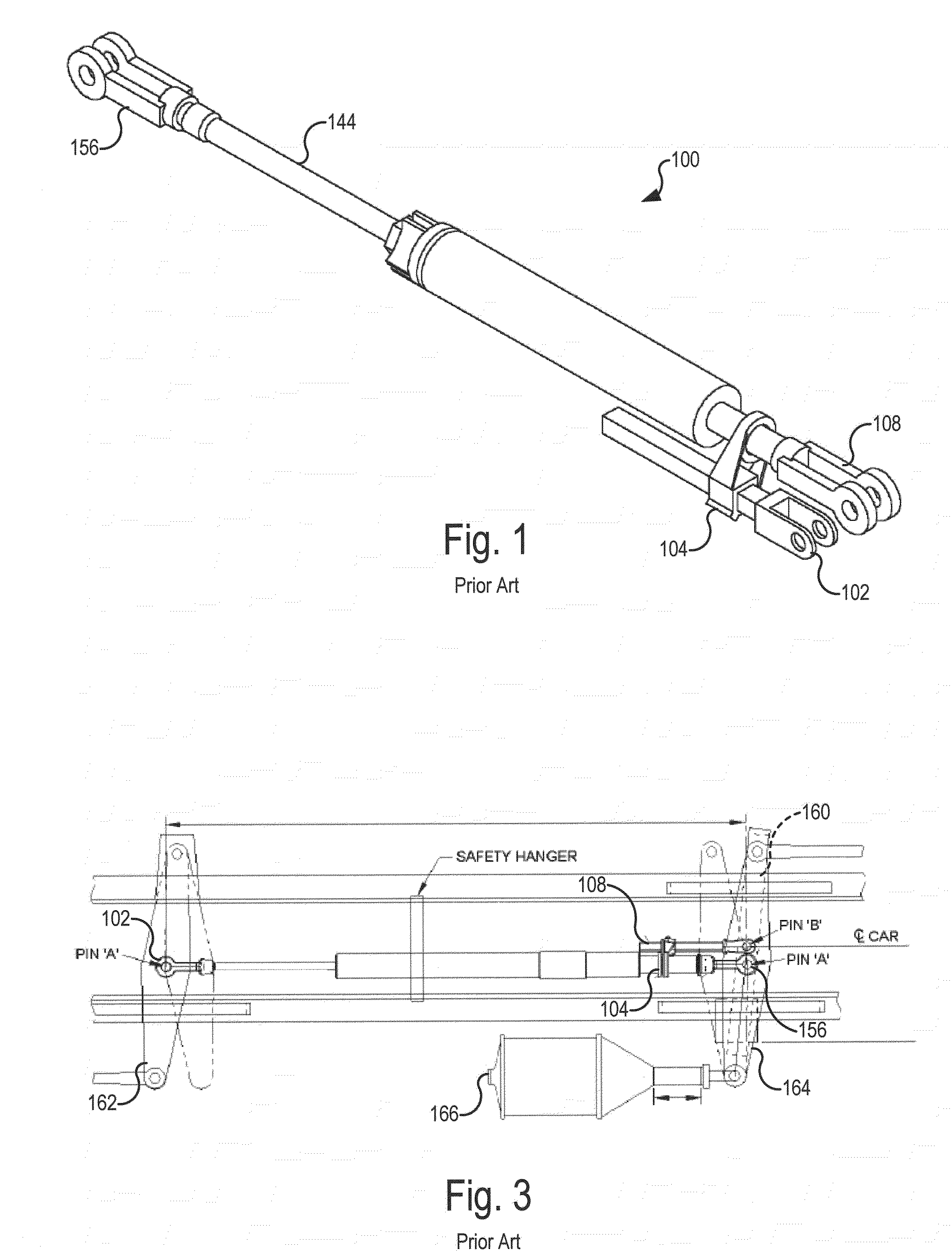
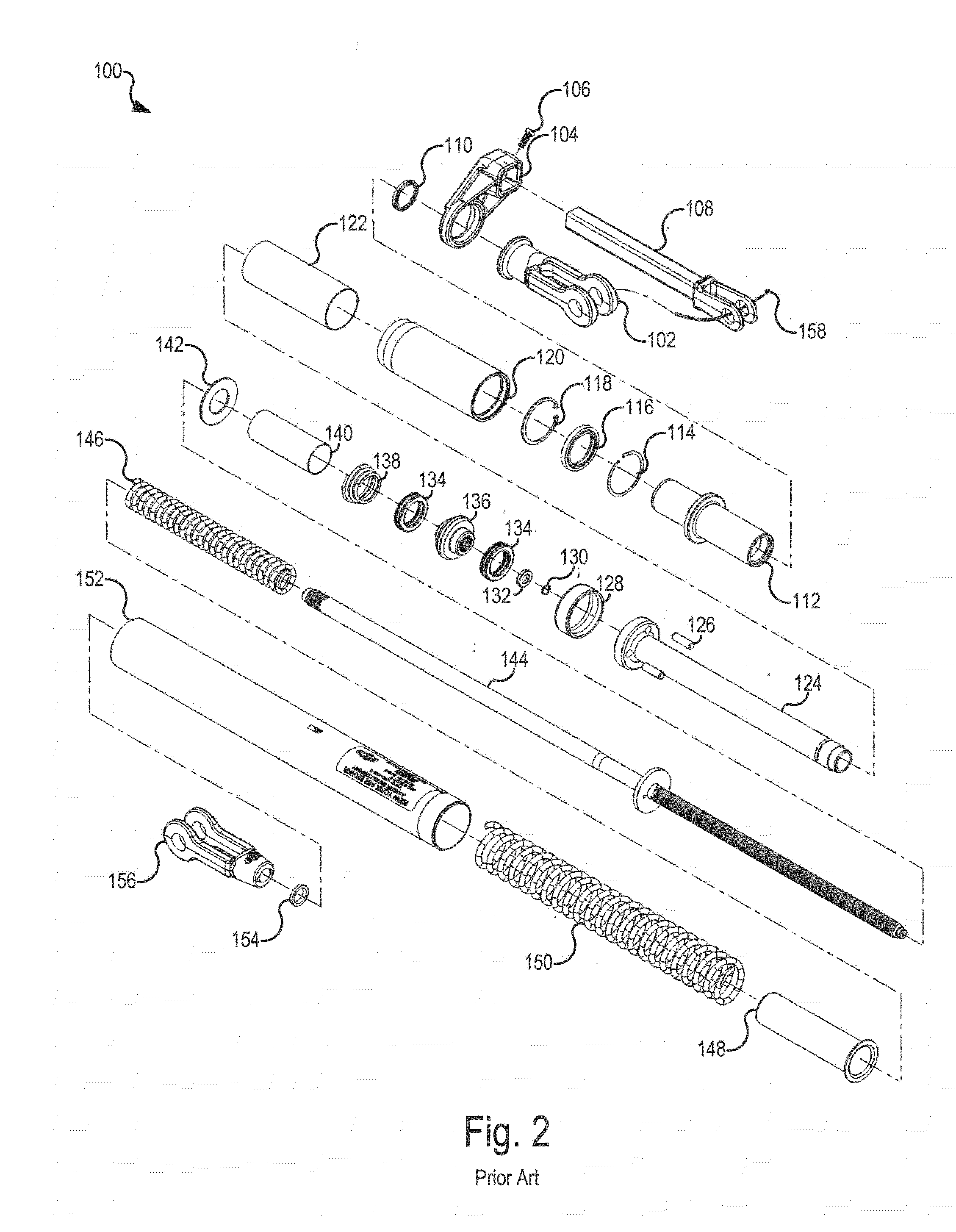
[0026]Referring now to the drawings, wherein like reference numerals and characters represent like or corresponding parts throughout each of the views, there is shown in FIGS. 1-3 a slack adjus...


PUM


Abstract

Embodiments of the invention provide one or more of the following features or combinations of such features to slack adjusters: rubber boots or bellows on either end of the slack adjuster to shed water away from the slack adjuster; a center vent and wasp excluder to vent any water build up in the slack adjuster clutch area; an added seal and wear ring at the slack adjuster end cap; and increased corrosion and wear protection for the rod.

Description

CROSS-REFERENCE TO RELATED APPLICATIONS[0001]This application claims the benefit of U.S. Provisional Application No. 61 / 764,230, filed Feb. 13, 2013, which is incorporated herein by reference.BACKGROUND OF THE INVENTION[0002]1. Field of the Invention[0003]Embodiments of the present invention relate generally to slack adjusters for use with railcar brake rigging. More particularly, embodiments of the present invention are directed to integrated slack adjusters with improved environmental protection.[0004]2. Statement of the Prior Art[0005]On many railcars, braking forces are transmitted from a brake cylinder to the brake shoes by a system of rods and levers called brake rigging. The three basic types of brake rigging for railcars are body-mounted brakes, truck-mounted brakes, and direct-acting cylinders. Body-mounted brake systems typically have one brake cylinder, mounted underneath the body of the railcar, which transmits braking forces to the brake shoes through a system of rods a...

Claims


Application Information

Patent Timeline
IPC IPC(8): F16D65/00B61H15/00F16D65/14B61H13/20F16D65/38
CPCB61H13/20B61H15/0057F16D65/0025F16D65/14F16D65/56F16D2121/08F16D2125/08
Inventor HUBER, JR., HOWARDWRIGHT, ERIC C.SAUTER, JEFF
Owner NEW YORK AIR BRAKE CORP
Why Eureka
Try Eureka