Calibration apparatus, and control method thereof

Inactive Publication Date: 2015-08-13
CANON KK
View PDF7 Cites 4 Cited by
  • Summary
  • Abstract
  • Description
  • Claims
  • Application Information

AI Technical Summary

Benefits of technology

The present invention helps to accurately detect when there is a problem with the calibration of a photometer or similar device. It also reduces the number of false alarms for inappropriate calibration execution.

Problems solved by technology

Specifically, the light from the display surface may not reach the light receiving unit of the photometer, or external light may enter the light receiving unit, which makes it impossible to acquire a correct measurement result.
If an incorrect measurement result is acquired, an incorrect calibration result is acquired.
As a result, the display characteristics diverge from the desired characteristics because of this incorrect calibration.
This means that an installation failure can be accurately detected in a dark room environment, which is not influenced by external light very much, on the other hand, in an environment which is easily influenced by external light, an installation failure is frequently detected, and calibration is often force-ended.

Method used


Image

  • Calibration apparatus, and control method thereof
  • Calibration apparatus, and control method thereof
  • Calibration apparatus, and control method thereof

Examples


example 1

[0028]Now a calibration apparatus according to Example 1 of the present invention and a control method thereof will be described. The calibration apparatus according to this example executes calibration of a display apparatus using a first measurement value, which is a measurement value of light from the screen of the display apparatus.

[0029]In this example, a case of the calibration apparatus that is disposed in the display apparatus will be described, but the calibration apparatus may be an apparatus that is separate from the display apparatus.

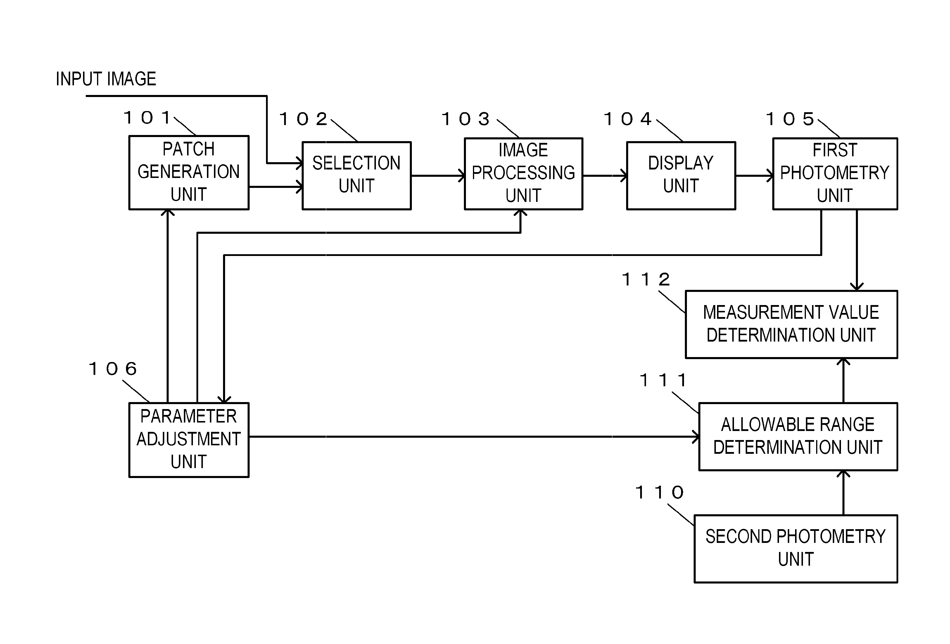
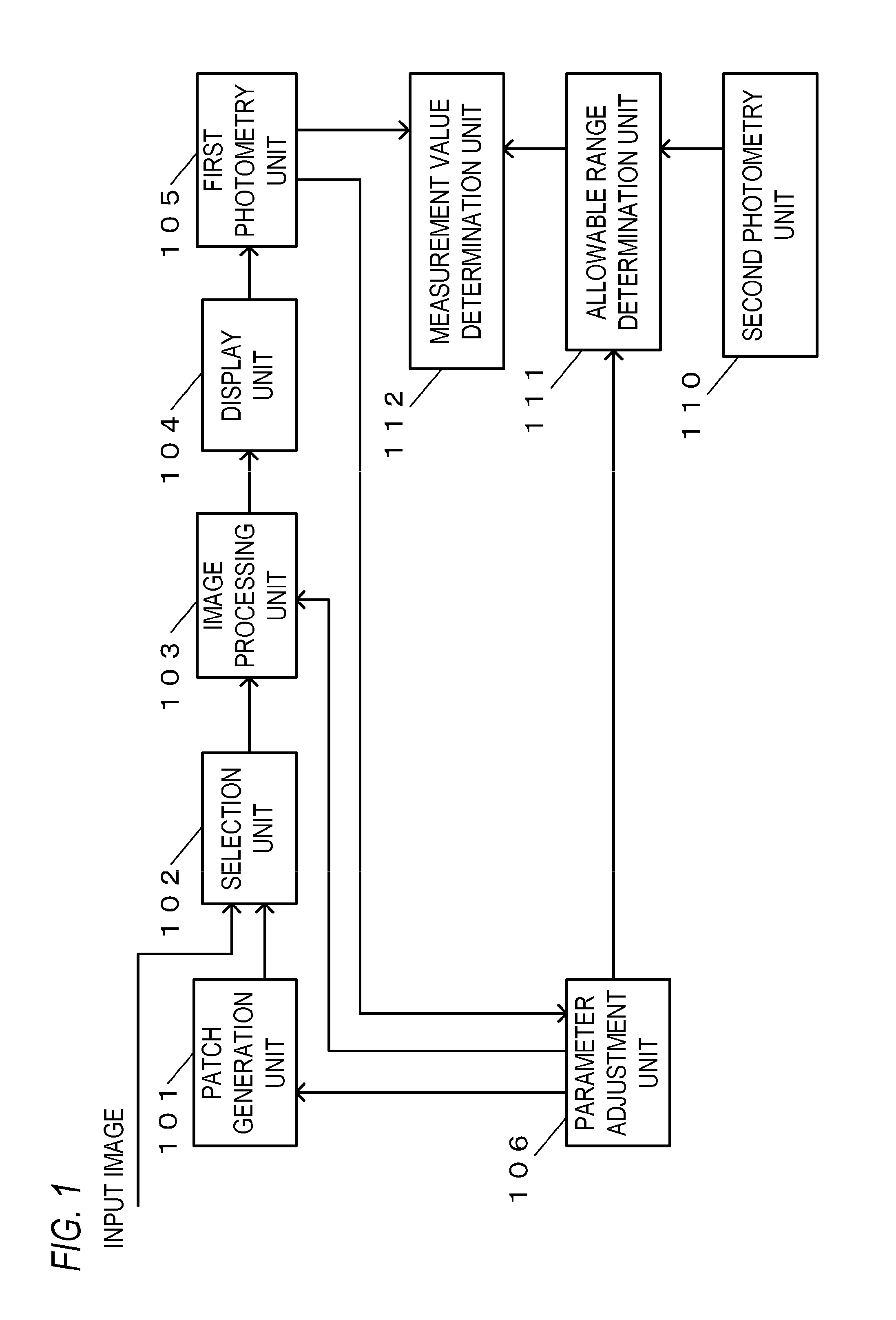
[0030]FIG. 1 is a block diagram depicting an example of a functional configuration of the display apparatus according to this example.

[0031]A patch generation unit 101 generates a patch image which is a target of image quality evaluation (evaluation target) during calibration. In this example, an image, where each pixel value is the same as the other pixel values (image of which color and brightness are uniform), is generated as the patch im...

example 2

[0146]Now a calibration apparatus according to Example 2 of the present invention, and a control method thereof, will be described.

[0147]Surface processing may be performed on the screen, and the degree of the influence of the external light on the first measurement value depends on the surface processing, and it is preferable to determine a wider allowable range as the degree of influence of the external light on the first measurement value is greater. Therefore in this example, an example of determining the allowable range, also considering the type of surface processing performed on the screen, will be described.

[0148]In concrete terms, if glare processing has been performed on the screen, then the external light is more easily reflected on the screen, and the external light more easily influences the first measurement value, compared with the case of a screen on which non-glare processing has been performed. Therefore in this example, a case of determining a wider allowable rang...


PUM


Abstract

A calibration apparatus according to the present invention includes: a first acquisition unit configured to acquire a first measurement value, which is a measurement value of light from a screen of a display apparatus; a second acquisition unit configured to acquire a second measurement value, which is a measurement value of external light to the display apparatus; an allowable range determination unit configured to determine an allowable range of the first measurement value based on the second measurement value acquired by the second acquisition unit; and a measurement value determination unit configured to determine whether the first measurement value acquired by the first acquisition unit is a value within the allowable range determined by the allowable range determination unit.

Description

BACKGROUND OF THE INVENTION[0001]1. Field of the Invention[0002]The present invention relates to a calibration apparatus and a control method thereof.[0003]2. Description of the Related Art[0004]Calibration is a known technique that makes the display characteristics of a display apparatus closer to the desired characteristics. In calibration, an evaluation image (patch image) is displayed on a display apparatus, and the optical characteristics (e.g. brightness and colors on the screen) of the evaluation image are measured by a photometer. Then the image quality of the evaluation image is adjusted so that the measured optical characteristics become closer to the desired characteristics. For example, the image quality is adjusted by adjusting the values of parameters which are used for image processing. By repeating display, measurement and image quality adjustment of the evaluation image, the display characteristics of the display apparatus can be brought closer (or maintained at) th...

Claims


Application Information

Patent Timeline
IPC IPC(8): H04N17/00
CPCH04N17/004H04N17/04G02B2207/00G06K1/00G06K2207/00
Inventor KOSUGE, TAKUYA
Owner CANON KK
Why Eureka
Try Eureka