
Magnetic toner

Inactive Publication Date: 2015-08-13
CANON KK
View PDF14 Cites 21 Cited by
  • Summary
  • Abstract
  • Description
  • Claims
  • Application Information

AI Technical Summary

Benefits of technology

The invention provides a magnetic toner that can maintain its performance even after long-term storage and has a broad fixation temperature range.

Problems solved by technology

In addition, the developing zone at the developing nip region is narrowed and fly over by the magnetic toner from the developing sleeve is then impaired and the magnetic toner with a weak charging performance, i.e., a weak developing strength, will readily remain on the developing sleeve.
In this case, turn over of the magnetic toner in the magnetic toner layer within the blade nip deteriorates and charge rise by the magnetic toner is impaired.
In particular, with magnetic toners the dispersibility of the magnetic body readily exercises a substantial effect on the charging performance, as compared to magnetic body-free nonmagnetic toners, and various image defects are readily produced when the rise in the amount of charge on the magnetic toner is impeded.
However, no mention is made in particular of the charge rising performance and the fixing performance when the magnetic body is incorporated as a colorant in the reasonable amount, and this is inadequate for obtaining the effects of the present invention.
In these inventions, however, the free ratio of the spherical particles or large-diameter particles, as inferred from the anchoring conditions or free conditions of these particles, is relatively high, and control of the state of attachment of inorganic fine particles that are otherwise added is inadequate.
Due to this, the charge rising performance for magnetic toners is inadequate—for example, when an extended durability test is run after storage in a high-temperature, high-humidity environment, under which circumstances the state of attachment of inorganic fine particles is already susceptible to variation—and the effects pursued by the present invention are not obtained.
They are also inadequate with regard to control of the resin composition and / or viscosity and are thus unsatisfactory from the standpoint of securing the fixation temperature region intended for the present invention.

Method used

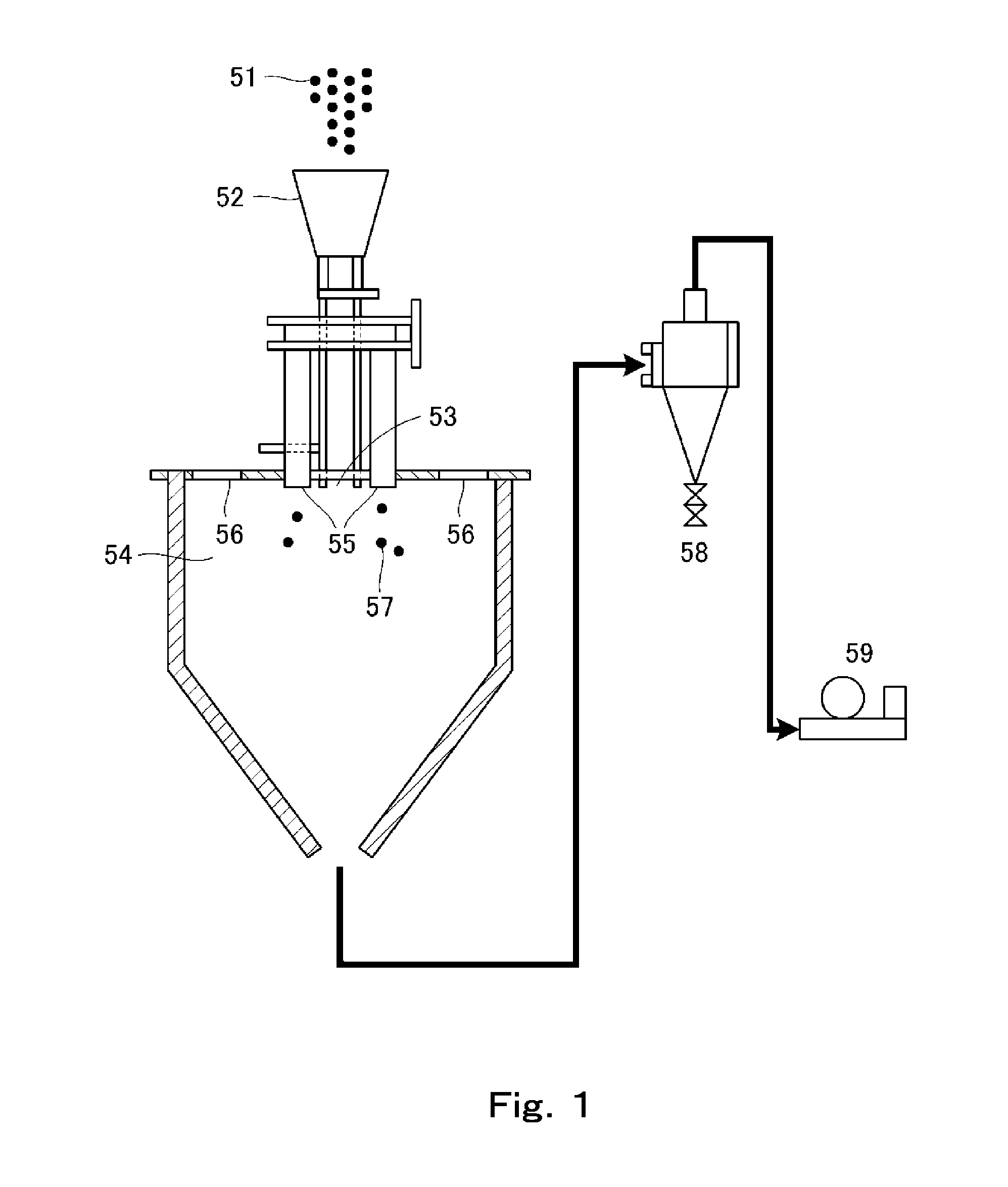
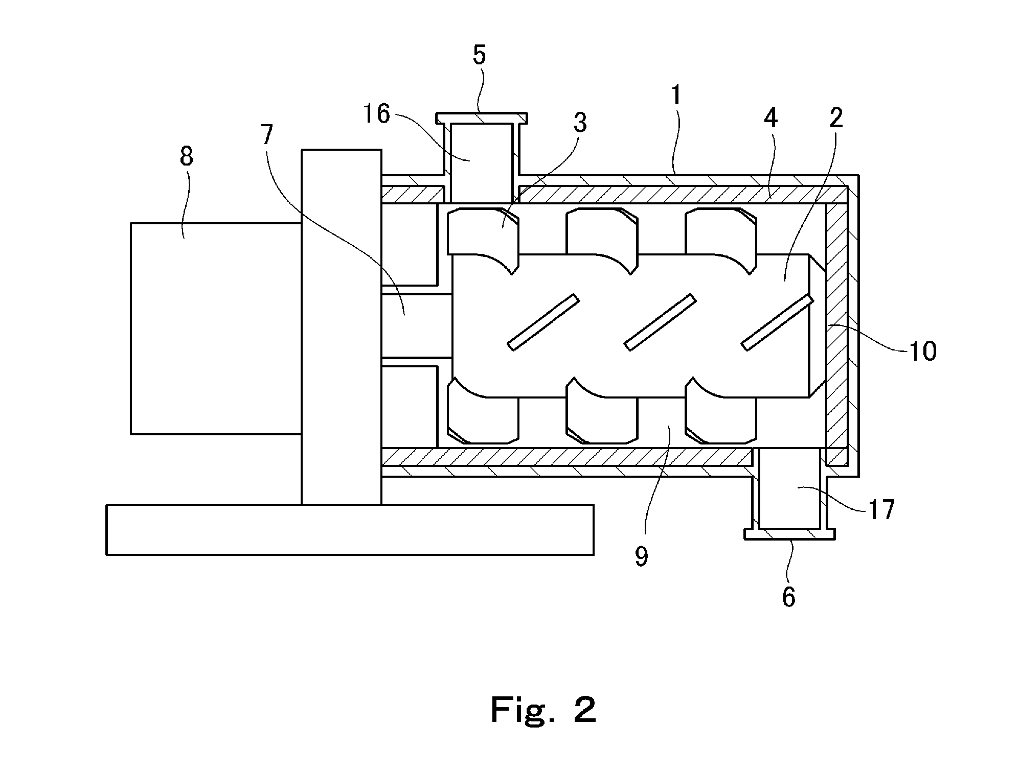
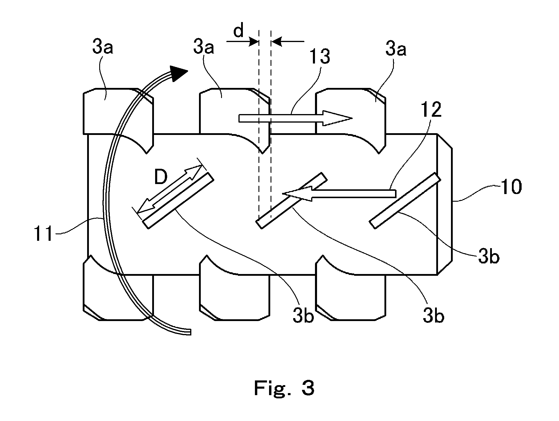

Image

  • Magnetic toner
  • Magnetic toner
  • Magnetic toner

Examples


example 1

Charge Rising Behavior

[0358]The charge rising behavior of the toner was evaluated as follows.

[0359]The magnetic toner at the back of the sleeve is recovered from the cartridge after the completion of the image output evaluation with the LBP3100 that is described below. 1.0 g of the recovered magnetic toner and 9.0 g of a resin-coated ferrite carrier are introduced into a 50-cc polyethylene bin. This bin is allowed to stand for 24 hours at normal temperature and normal pressure and is thereafter placed in a shaker (Yayoi Co., Ltd.) and is shaken for 10 seconds at a speed of 100 back-and-forth excursions per minute, after which the quantity of charge is measured using the charge quantity measurement device shown in FIG. 8.

[0360]This method for measuring the quantity of charge will be described in detail. First, with regard to the quantity of charge, approximately 0.5 to 1.5 g of the toner and carrier mixture is introduced after shaking into a metal measurement container 202 having a 5...


PUM

PropertyMeasurementUnit
Temperatureaaaaaaaaaa

Abstract

The magnetic toner contains a magnetic toner particle having a binder resin and a magnetic body, and inorganic fine particles, wherein the average circularity of the magnetic toner is at least 0.955 and, when classifying the inorganic fine particles, in accordance with the fixing strength thereof to the magnetic toner particle and in the sequence of the weakness of the fixing strength, as first inorganic fine particles, second inorganic fine particles, and third inorganic fine particles, the content of the first inorganic fine particles, the ratio of the second inorganic fine particles to the first inorganic fine particles, and the coverage ratio X are in prescribed ranges.

Description

TECHNICAL FIELD[0001]The present invention relates to a magnetic toner that is used in recording methods that use, for example, an electrophotographic method.BACKGROUND ART[0002]Image-forming apparatuses, e.g., copiers and printers, have in recent years been subjected to greater diversity in their intended uses and use environments as well as demands for greater speed, higher image quality, and greater stability. For example, printers, which in the past have been used mainly in the office, have also entered into use in severe environments, e.g., high temperatures, high humidities, and it is critical even in such instances that a stable image quality be provided.[0003]Copiers and printers are also undergoing apparatus downsizing as well as advances in energy efficiency, and the use is preferred within this context of magnetic single-component developing systems that use a favorable magnetic toner.[0004]In a magnetic single-component developing system, a magnetic toner layer is formed...

Claims


Application Information

Patent Timeline
IPC IPC(8): G03G9/083G03G9/087
CPCG03G9/0839G03G9/083G03G9/08711G03G9/0821G03G9/0827G03G9/0835G03G9/0836G03G9/08706G03G9/08795G03G9/09708G03G9/09725
Inventor SANO, TOMOHISAHASEGAWA, YUSUKEHIROKO, SHUICHISUZUMURA, YOSHITAKATANAKA, KEISUKE
Owner CANON KK
Learn More