Motorized vehicle

a motorized vehicle and folding technology, applied in the field of folding motorized vehicles, can solve the problems of difficult storage of personal mobility vehicles, and certain personal mobility vehicles

Active Publication Date: 2015-07-30
MOVING LIFE LTD
View PDF7 Cites 35 Cited by
  • Summary
  • Abstract
  • Description
  • Claims
  • Application Information

AI Technical Summary

Benefits of technology

[0009]According to some embodiments of the present invention, there is provided a motorized vehicle having a wheel retraction apparatus. The motorized vehicle comprises a plurality of rear wheels and at least one front wheel, a lower chassis having a foot surface mounted thereon, and a wheel retraction apparatus mechanically connected to the lower chassis and set to extract and retract the plurality of rear wheels from and towards the lower chassis and to fixate the plurality of rear wheels in a plurality of different widths from one another. A distance between an axis passing through the centers of the plurality of rear wheels and the at least one front wheel does not increase when the plurality of rear wheels are retracted towards the lower chassis.
[0031]According to some embodiments of the present invention, there is provided a motorized vehicle having a sitting configuration and a standing configuration. The vehicle comprises a steering rod, a lower chassis which is connected to the steering rod and supports at least one rear wheel and at least one front wheel and having a foot surface for supporting feet of a user while the motorized vehicle is driven by the user in a sitting position, an upper chassis having a backrest connected to a seat base by a seat bearing, and at least one bearing which connects between the lower chassis and the upper chassis and allows switching between a sitting configuration and a standing configuration of the motorized vehicle by bringing the backrest from being substantially perpendicular to the foot surface to be in a proximity with and substantially in parallel to the foot surface. The steering rod is substantially perpendicular to the foot surface while the motorized vehicle is driven by the user in any of the sitting configuration and the standing configuration.
[0035]According to some embodiments of the present invention, there is provided a central lock and release mechanism simultaneously operating two locks when folding a motorized vehicle. The lock comprises a lower chassis having a front lower chassis and a rear lower chassis, a steering rod, a steering rod lock connecting the steering rod and the front lower chassis, a lower chassis lock connecting the front lower chassis and the rear lower chassis, a motion transferring element connecting the steering rod lock and the lower chassis lock, a handle; and a puller mounted on the handle. The motorized vehicle is folded by lifting the handle and the handle pulls the puller and the puller opens a first lock of the steering rod lock and the lower chassis lock and the first lock moves the motion transferring element and the motion transferring element opens second lock of the steering rod lock and the lower chassis lock and open the steering rod lock enable folding of the steering rod towards the lower chassis and open the lower chassis lock enables folding of the lower chassis so the front lower chassis and the rear lower chassis are in close proximity.
[0040]According to some embodiments of the present invention, there is provided a central lock and release mechanism of a motorized vehicle that comprises a lower chassis having a front lower chassis and a rear lower chassis, a first rear lower chassis pin mounted on the rear lower chassis, a second rear lower chassis pin mounted on the rear lower chassis, a handle, a puller mounted on the handle, an axis mounted on the front lower chassis, a rocker pivoting around the axis, having a fork hook, a first rear lower chassis hook and a second rear lower chassis hook, a rocker spring connected to the rocker, a fork mounted on the front lower chassis, having a pin fitting the fork hook, a flange mechanically connected to the rear lower chassis, and a flange spring connected to the flange. The central lock and release mechanism is released from locking an operational configuration of a motorized vehicle by lifting the handle and pulling the puller and the puller pivots the rocker against the rocker spring thereby releases the first rear lower chassis hook and the fork hook so that the front lower chassis and the rear lower chassis are free to move from an operative configuration to a folded configuration and the central lock and release mechanism locks a folded configuration of a motorized vehicle by the second rear lower chassis hook hooking to the rear lower chassis and the rocker and the fork geometrically limit the steering rod thereby restricting the steering rod tilting.

Problems solved by technology

Although known personal mobility vehicles provide the desired mobility to the user, the known personal mobility vehicles suffered from certain disadvantages.
Firstly, the known personal mobility vehicles are difficult to store during nonuse of the personal mobility vehicle.
In general, the size of the known personal mobility vehicles prohibited the storage of the personal mobility vehicle within a closet or a small room.
Secondly, the known personal mobility vehicles are difficult to transport in a conventional automobile.
Thirdly, the known personal mobility vehicles are difficult to lift in an assembled condition.
Unfortunately, because of the overall size of the assembled known personal mobility vehicles, a lift, hoist or two individuals were required in order to lift the personal mobility vehicle from the ground to the luggage compartment of the small truck, small van or the sports utility vehicle.

Method used


Image

  • Motorized vehicle
  • Motorized vehicle
  • Motorized vehicle

Examples


Embodiment Construction

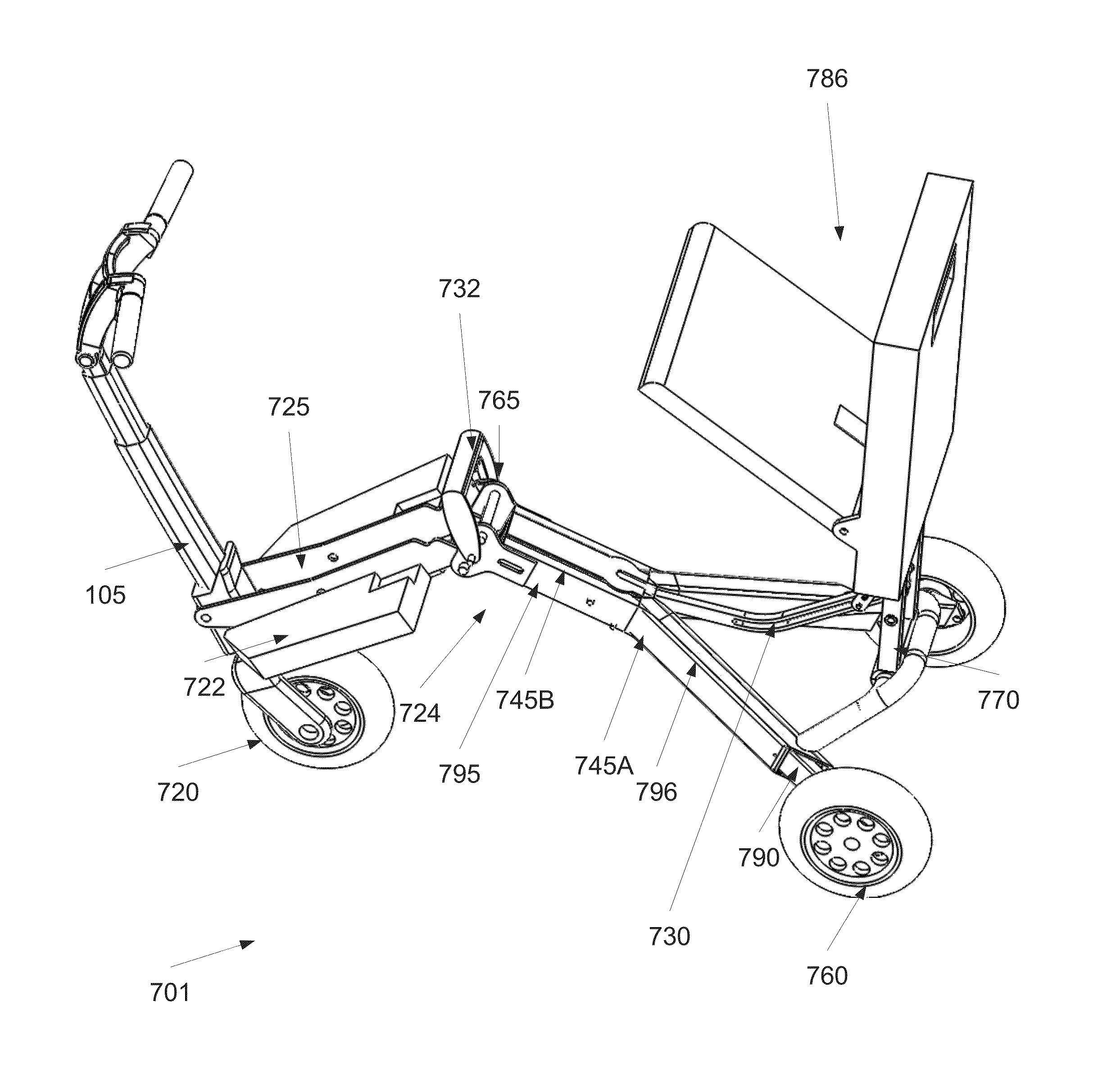
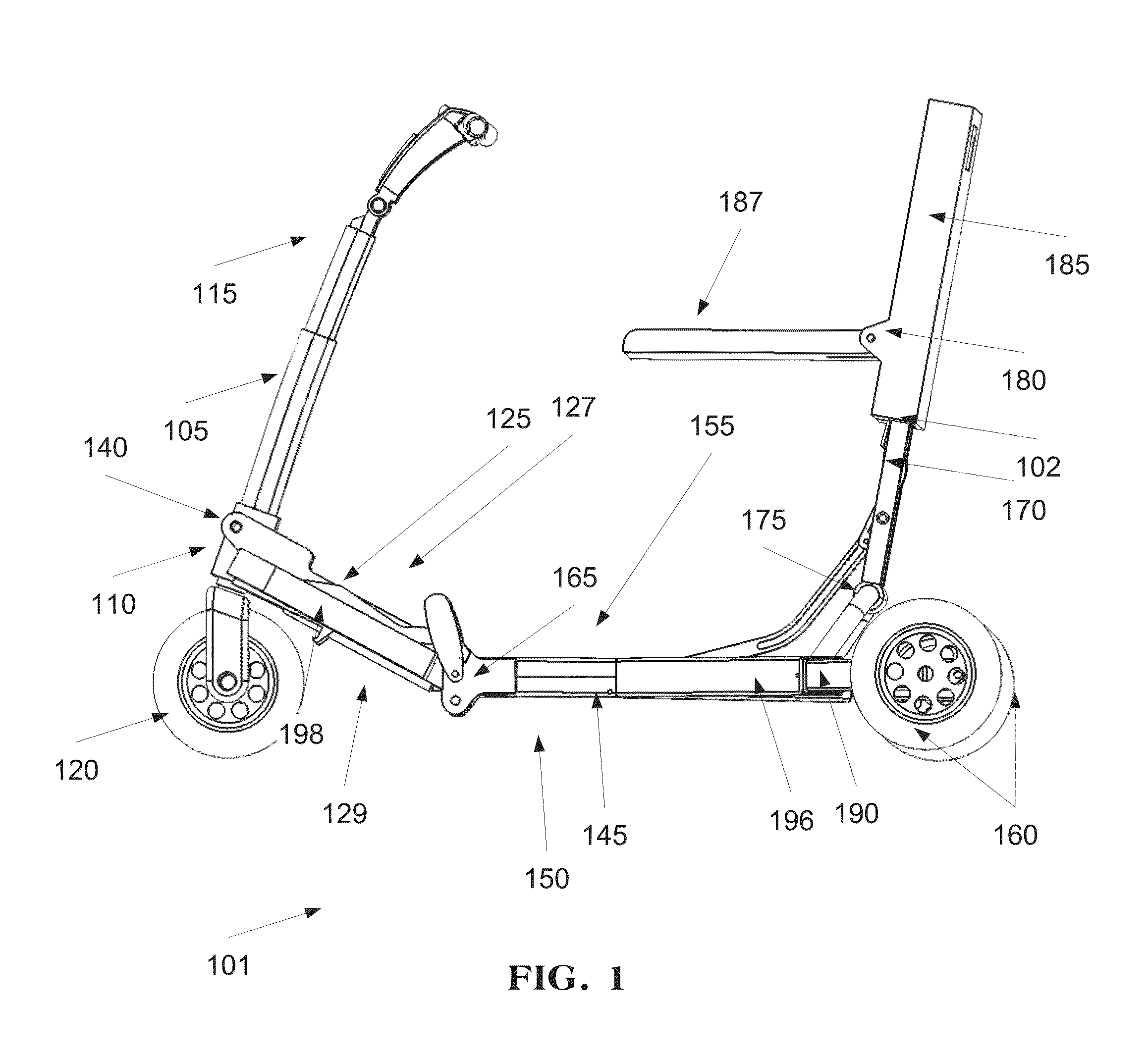
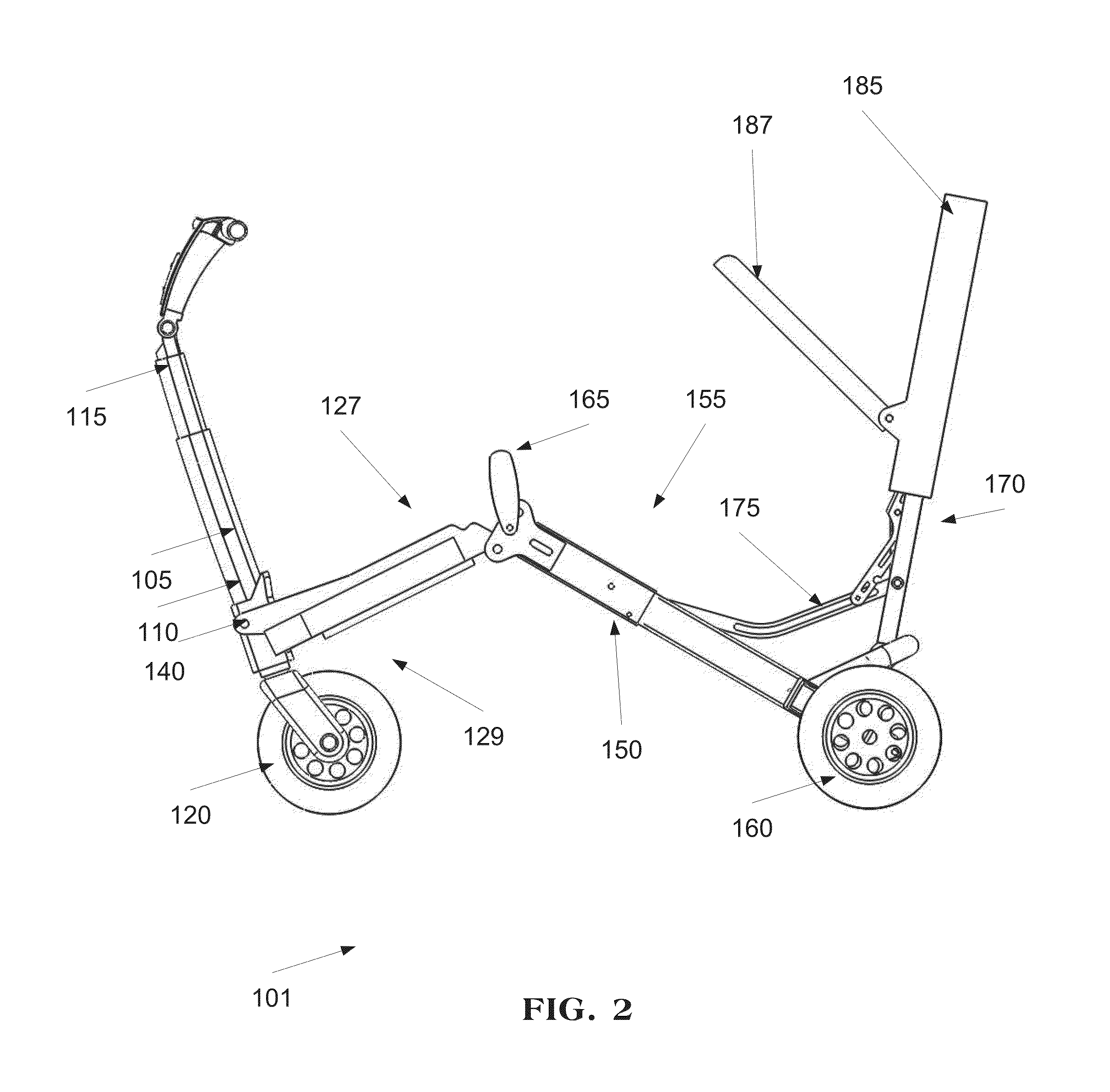
[0113]The present invention, in some embodiments thereof, relates to motorized vehicles and, more particularly, but not exclusively, to a foldable motorized vehicle.

[0114]The present invention, in some embodiments thereof, relates to a motorized vehicle having a folded trolley shaped configuration wherein the width of the folding mobility scooter is no more than a width of an aircraft trolley and a sitting configuration wherein the distance between the rear wheels provides stability, for example under mobility scooter regulations. Optionally, the motorized vehicle folds in a fanfold bringing the front wheel and the rear wheels close to one another. Optionally, the motorized vehicle has a standing configuration having the same distance between its rear wheels as the folded configuration.

[0115]The present invention, in some embodiments thereof, relates to a mechanism for retracting rear wheels. The rear wheels move diagonally with respect to the chassis. The distance between the rear ...


PUM


Abstract

A motorized vehicle having a wheel retraction apparatus, comprising: a plurality of rear wheels and at least one front wheel; a lower chassis having a foot surface mounted thereon; and a wheel retraction apparatus mechanically connected to said lower chassis and set to extract and retract said plurality of rear wheels from and towards said lower chassis and to fixate said plurality of rear wheels in a plurality of different widths from one another; wherein a distance between an axis passing through the centers of said plurality of rear wheels and said at least one front wheel is reduced when said plurality of rear wheels are retracted towards said lower chassis.

Description

FIELD AND BACKGROUND OF THE INVENTION[0001]The present invention, in some embodiments thereof, relates to motorized vehicles and, more particularly, but not exclusively, to a foldable motorized vehicle.[0002]The popularity of personal mobility vehicles has dramatically increased over the last several decades. This increase in the popularity of personal mobility vehicles is due to many factors including the advent of new structural material as well as new manufacturing techniques.[0003]Although known personal mobility vehicles provide the desired mobility to the user, the known personal mobility vehicles suffered from certain disadvantages. Firstly, the known personal mobility vehicles are difficult to store during nonuse of the personal mobility vehicle. In general, the size of the known personal mobility vehicles prohibited the storage of the personal mobility vehicle within a closet or a small room. Secondly, the known personal mobility vehicles are difficult to transport in a con...

Claims


Application Information

Patent Timeline
Patent Type & Authority Applications(United States)
IPC IPC(8): A61G5/08B62K5/025
CPCA61G5/08B62K5/025A61G2005/0883A61G2005/0866A61G2005/0825B62K15/008A61G5/0825A61G5/0866A61G5/0883B62K5/02
Inventor RANSENBERG, ABRAHAM-NINOARTSIELY, EYALBAR EREZ, ARIKBROT, MOR MICHAELCHOMSKI, YUVALGOLDMAN, YIZHAQGOREN, YAROM
Owner MOVING LIFE LTD
Why Eureka
Try Eureka