Scanning telescope

Active Publication Date: 2015-06-25
RAYTHEON CO
View PDF3 Cites 6 Cited by
  • Summary
  • Abstract
  • Description
  • Claims
  • Application Information

AI Technical Summary

Benefits of technology

This patent describes a scanning telescope system for use in a missile. The system includes a primary mirror, secondary mirror, tertiary mirror, and quaternary mirror that work together to focus electromagnetic radiation onto an imaging detector. The mirrors are designed to optimize the use of space in the missile and can scan a field of view over a range of angles. The system is designed to be mounted in a missile and can be used with infrared radiation. The technical effects of this system include improved optical imaging in a missile and improved efficiency in using space within the missile.

Problems solved by technology

Therefore, off-axis optical system designs, or on-axis designs that are optically folded using a flat mirror, are not good solutions for such applications.

Method used


Image

  • Scanning telescope
  • Scanning telescope
  • Scanning telescope

Examples


Embodiment Construction

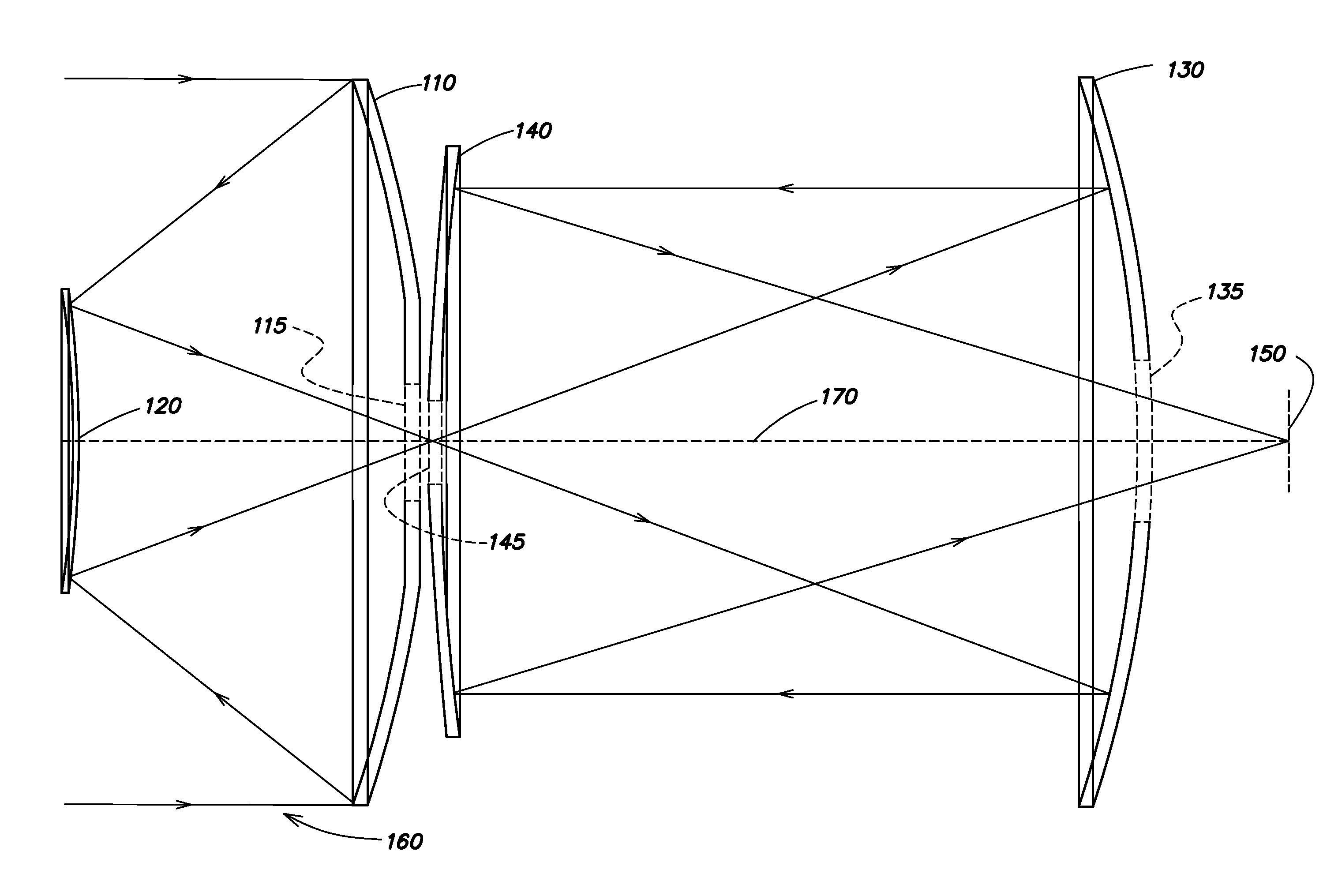
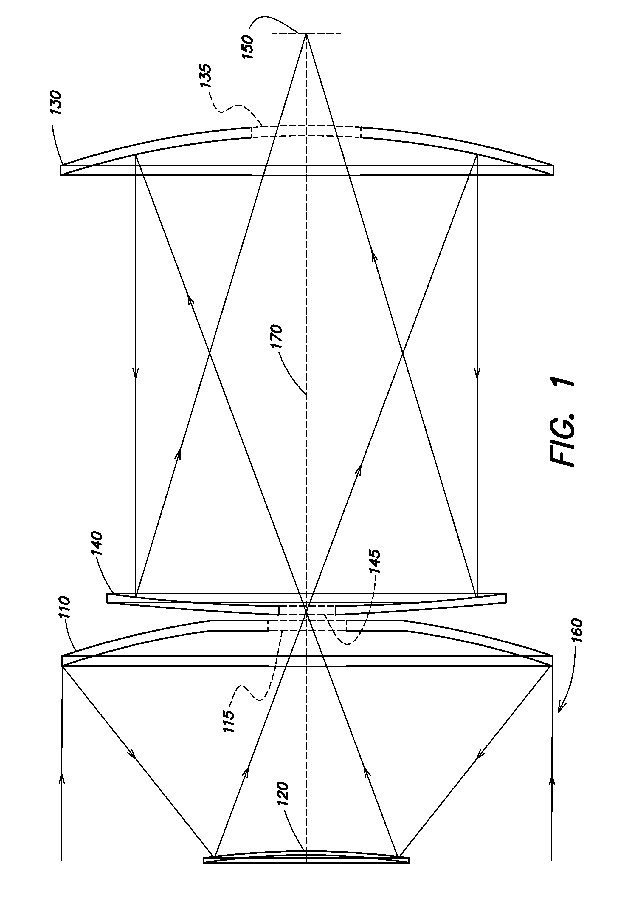
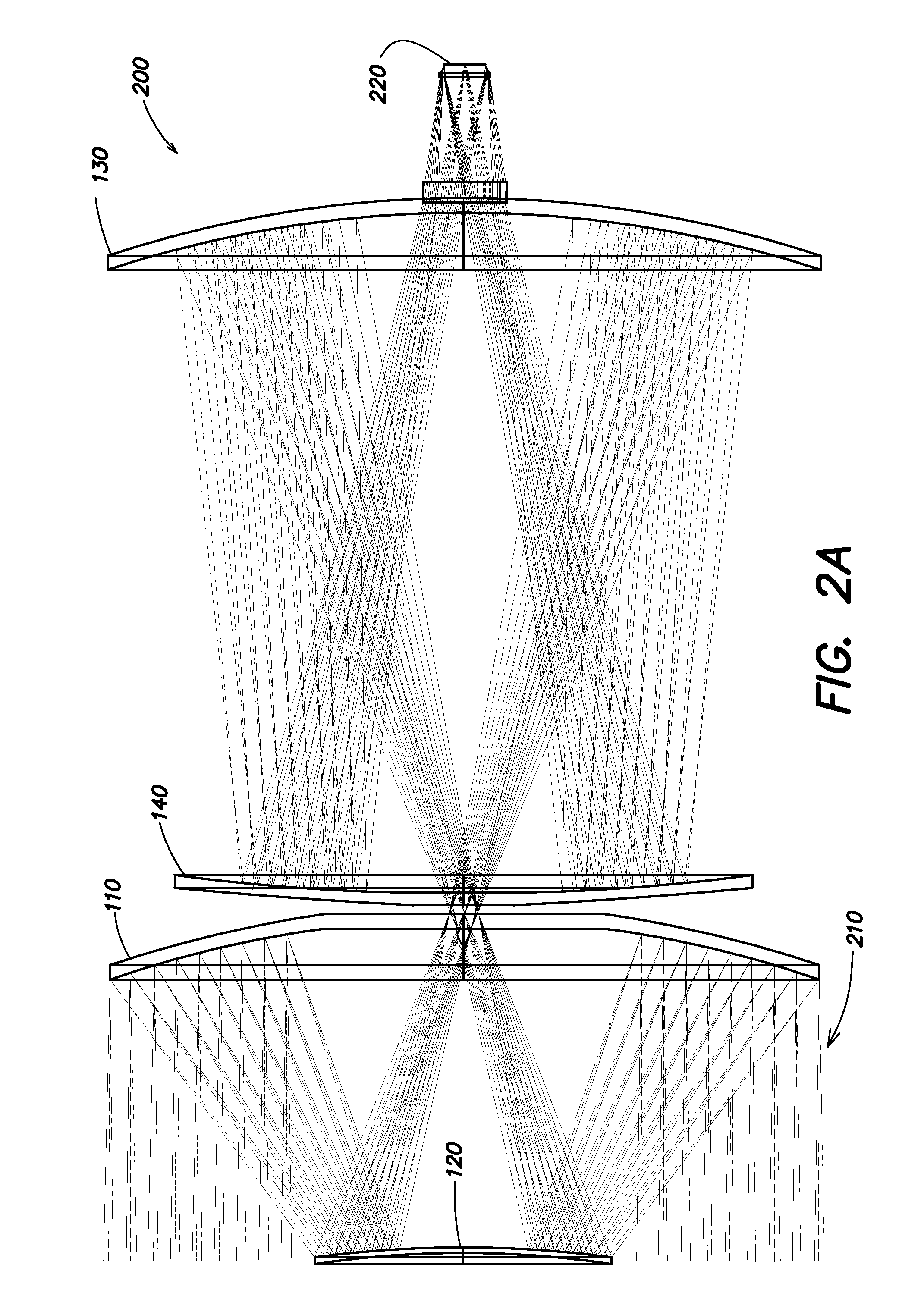
[0017]A missile has aerodynamic requirements that dictate a small frontal cross-section. This small cross-section limits the optical aperture available for light collection. Applications such as missile defense require as large an aperture as possible to collect as much light as possible and to improve the diffraction limited performance. Some prior scanning telescope systems for missile-based applications have used off-axis designs, which typically do not maximize the available aperture size, and additionally have used a gimbaled system to achieve scanning. As a result, the scan rate is relatively low since a large mass (the telescope and detector assembly) must be moved; however, these systems may achieve a relatively large field of regard. Aspects and embodiments are directed to a scanning telescope in which a low-mass moving element is used for scanning, thereby allowing high speed scan motion to be achieved. Additionally, certain aspects and embodiments may be optimal for missi...


PUM


Abstract

A scanning telescope including an on-axis four-mirror reflective telescope configured to receive electromagnetic radiation through an optical aperture and to direct and focus the electromagnetic radiation onto an imaging detector, the on-axis four-mirror reflective telescope including a rear-most mirror configured to be movable over a range of angular tilt relative to an optical axis of the scanning telescope to scan a field of view of the imaging detector over a scan range. In one example, the rear-most scanning mirror is the tertiary mirror of the four-mirror reflective telescope, and all four mirrors are axisymmetric about the optical axis of the telescope.

Description

BACKGROUND[0001]Optical imaging systems typically comprise a detector, usually placed within a housing having an aperture through which the detector may view an external scene, and a telescope that images the external scene onto the detector. Certain optical imaging applications require the ability to scan the field of view of the optical system over a wider field of regard. Existing systems for such application include off-axis telescope designs with flat, fast steering mirrors for scanning. For many applications, the optical subsystem must be as compact as possible, while remaining consistent with required optical performance for high quality imaging. For example, some missile systems require an optical system capable of scanning over small angles with high performance in the infrared spectral bands. Since the diffraction limited imaging resolution is limited by the aperture size, many applications of such missile systems require the aperture to use a very large fraction of the fr...

Claims


Application Information

Patent Timeline
IPC IPC(8): G02B23/02G02B5/10F42B15/01G02B17/08
CPCG02B23/02F42B15/01G02B5/10G02B17/0836F41G7/2253F41G7/2293G02B17/084G02B26/10
Inventor THERIAULT, PHILIP C.
Owner RAYTHEON CO
Why Eureka
Try Eureka