Supercharge Your Innovation With Domain-Expert AI Agents!

Image forming apparatus, jobs display and execution method, and recording medium

Active Publication Date: 2015-06-18
KONICA MINOLTA INC
View PDF7 Cites 0 Cited by
  • Summary
  • Abstract
  • Description
  • Claims
  • Application Information

AI Technical Summary

Benefits of technology

The present invention relates to an image forming apparatus with a display and a main memory. The apparatus can input and store job information with job reference information, which indicates the job details including the job name. The apparatus can then read the job information from the main memory to execute the job. The apparatus can also display a job name list based on the job reference information, which users can update by manipulating the display. The invention allows for efficient job execution and management.

Problems solved by technology

While executing an input job, for example, such an image forming apparatus often has a lack of sufficient RAM available for a subsequently input job, which is an unsolved problem.
Since users instantly finish manipulation, e.g., finger flicking, this image forming apparatus is required to update the list on the display quickly; unless it does it quickly, a negative user experience could be caused.
Even having the functions of: displaying a list of job names, updating the list, and showing detail information of a selected job, as described above, the conventional image forming apparatus, which is configured to save waiting jobs on a recording device form the RAM, still has a unsolved problem as described below.
To display a list of job names or update the list on the display, the conventional image forming apparatus takes time to restore job names on the RAM from the recording device, which negatively affects the quickness of a response to user manipulation.
Similarly, to display detail information of a selected job name, the conventional image forming apparatus takes time to restore the job reference information on the RAM from the recording device, which also negatively affects the quickness of a response to user manipulation.
This is a problem in operability to be solved.

Method used


Image

  • Image forming apparatus, jobs display and execution method, and recording medium
  • Image forming apparatus, jobs display and execution method, and recording medium
  • Image forming apparatus, jobs display and execution method, and recording medium

Examples


Embodiment Construction

[0054]In the following paragraphs, some preferred embodiments of the invention will be described by way of example and not limitation. It should be understood based on this disclosure that various other modifications can be made by those in the art based on these illustrated embodiments.

[0055]Hereinafter, some embodiments of the present invention will be described with reference to the accompanying figures.

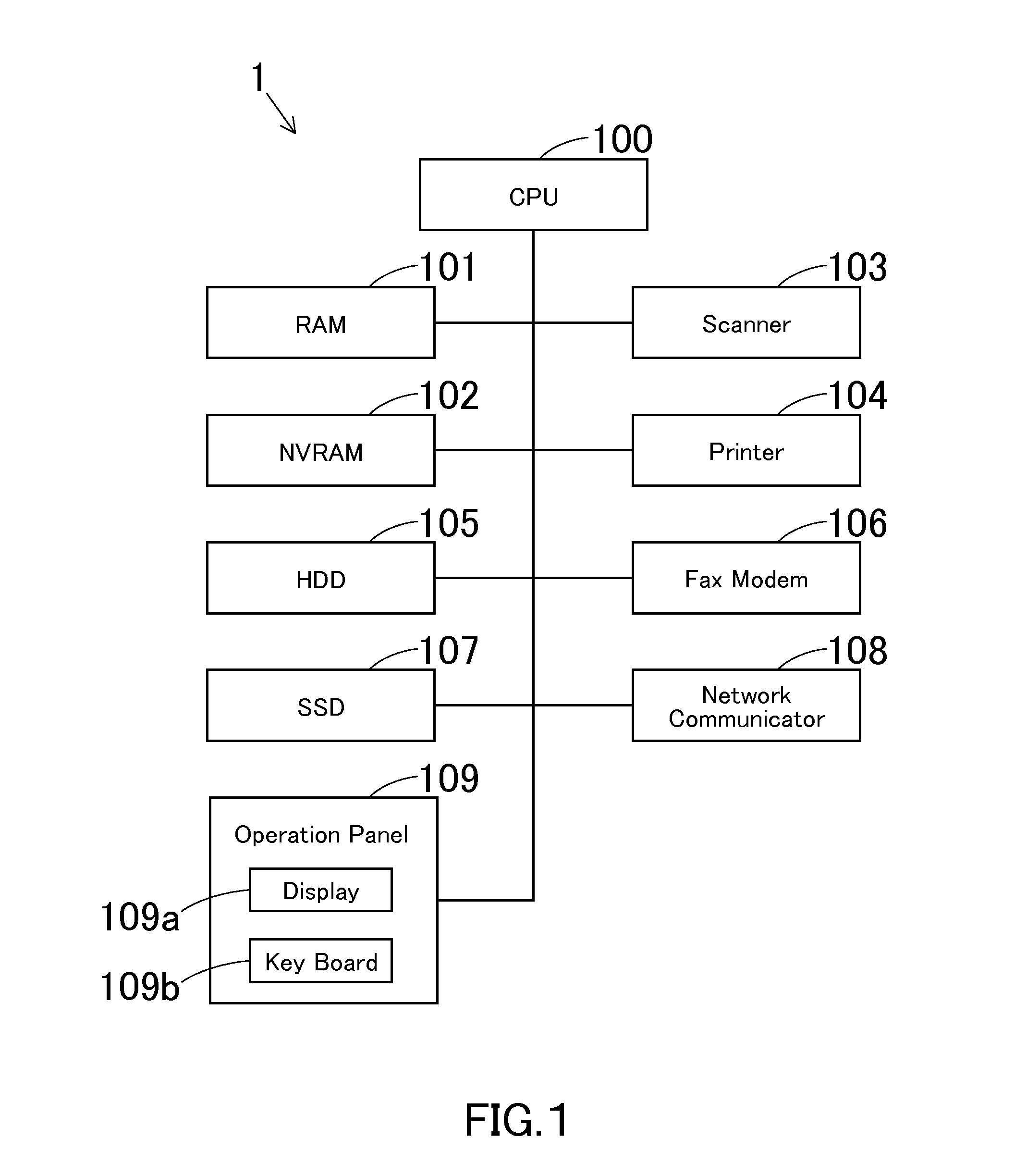
[0056]FIG. 1 is a block diagram illustrating a basic configuration of an image forming apparatus 1 according to one embodiment of the present invention. In this embodiment, a MFP having various functions such as a copier function, a printer function, and a scanner function, as described above, is employed as the image forming apparatus 1.

[0057]The image forming apparatus 1 is provided with: a CPU 100; a random access memory (RAM) 101; a non-volatile random access memory (NVRAM) 102; a scanner 103; a printer 104; a memory device 105; a facsimile (fax) modem 106; a solid state drive...


PUM


Abstract

An image forming apparatus includes: a display; a job input portion that inputs one or more jobs each having job and job reference information; a main memory; a job executor that executes the one or more jobs; a judgment portion that judges whether or not the one or more jobs can be executed; a first controller that stores the job and job reference information on the main memory if the one or more jobs can be executed or that stores the job and job reference information on the same and saves the job information on a recording device if the one or more jobs cannot be executed; a second controller that shows and updates a job name list and shows job details of a user's selected job name, all on the basis of the job reference information; and a third controller that restores the job information on the main memory.

Description

[0001]This application claims priority under 35 U.S.C. §119 to Japanese Patent Application No. 2013-260690 filed on Dec. 17, 2013, the entire disclosure of which is incorporated herein by reference in its entirety.BACKGROUND OF THE INVENTION[0002]1. Field of the Invention[0003]The present invention relates to: an image forming apparatus, i.e., a multi-function peripheral (MFP) such as a multifunctional digital machine; a jobs display and execution method to be implemented by the image forming apparatus; and a non-transitory computer-readable recording medium storing a jobs display and execution program for allowing a computer of the image forming apparatus to implement the jobs display and execution method.[0004]2. Description of the Related Art[0005]The following description sets forth the inventor's knowledge of related art and problems therein and should not be construed as an admission of knowledge in the prior art.[0006]To reduce the product cost, an image forming apparatus may...

Claims


Application Information

Patent Timeline
IPC IPC(8): H04N1/21H04N1/00
CPCH04N1/00408H04N1/2179H04N1/3263H04N1/32667
Inventor SUGIYAMA, TAKANOBU
Owner KONICA MINOLTA INC
Features
  • R&D
  • Intellectual Property
  • Life Sciences
  • Materials
  • Tech Scout
  • Unparalleled Data Quality
  • Higher Quality Content
  • 60% Fewer Hallucinations
Learn More