
Device for monitoring a sensor of a vehicle

a technology for monitoring devices and sensors, applied in the direction of instruments, fluid pressure measurement, heat measurement, etc., can solve the problems of redundant sensors, inability to readily determine which of the sensors is operating and the sensor is working in a faulty manner

Active Publication Date: 2015-06-11
ROBERT BOSCH GMBH
View PDF9 Cites 51 Cited by
  • Summary
  • Abstract
  • Description
  • Claims
  • Application Information

AI Technical Summary

Benefits of technology

The present invention is a method that uses wireless communication to compare the measured values of a vehicle's sensors with those of another vehicle. This helps to gather valuable information and improve safety and efficiency in vehicles.

Problems solved by technology

If the offset of a sensor is too large, that is, it is outside a tolerance range, one may assume that the sensor is working in a faulty manner.
The disadvantage with known methods is that, depending on the type of sensor to be monitored, redundant sensors have to be present.
In a comparison of only 2 present sensors, it cannot be readily determined which of the sensors is operating in a faulty manner.
In addition, the abovementioned method cannot be used at all times, since stable operating states of the internal combustion engine have to be present.
If only one comparison vehicle is available for the comparison of the measured values, when the measured values deviate, it is at first not possible to decide which of the compared values is faulty.

Method used


Image

  • Device for monitoring a sensor of a vehicle
  • Device for monitoring a sensor of a vehicle
  • Device for monitoring a sensor of a vehicle

Examples


Embodiment Construction

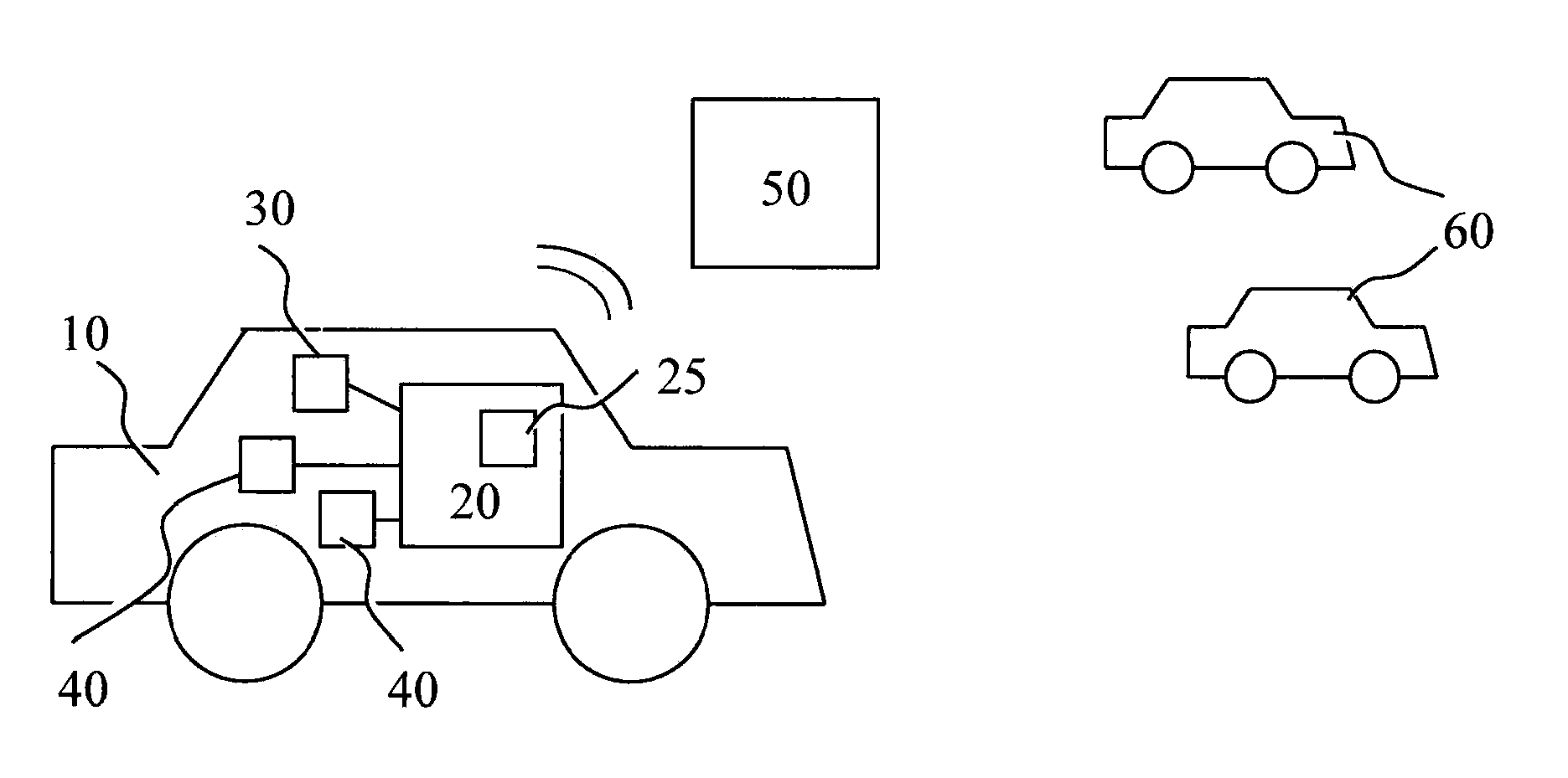
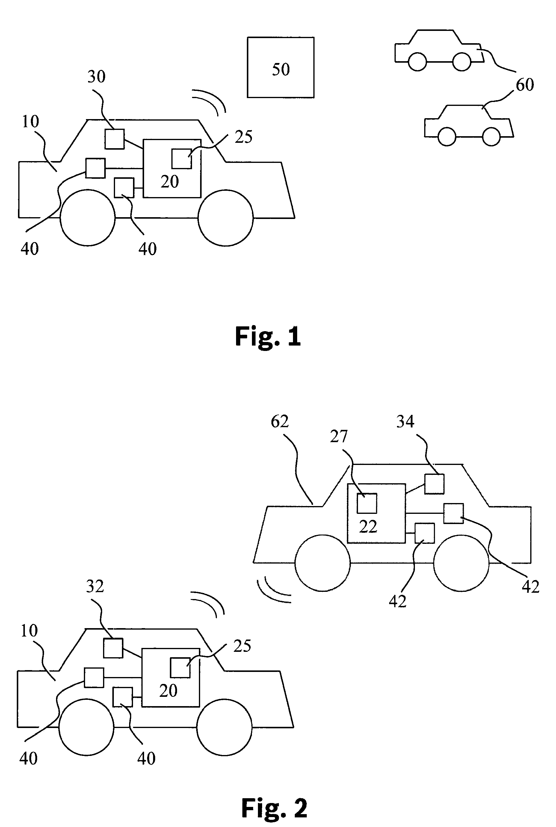
[0023]FIG. 1 shows a vehicle 10 having a device for carrying out the method according to the present invention according to a first exemplary embodiment. Vehicle 10 has an electronic arithmetic unit 20 which is advantageously an electronic control unit, such as an engine control that is present anyhow. The method according to the present invention may also, however, run on other electronic control units, which are either already installed in vehicle 10 for other reasons, or for carrying out the method according to the present invention.

[0024]Electronic control unit 20 includes an electronic storage medium 25, on which a computer program is stored that is developed to carry out each step of the method according to the present invention. The electronic storage medium is also used, for example, to store sensor data, results of comparisons, assessments of the state of sensors or characteristic curves of sensors.

[0025]Vehicle 10 has at least one sensor 40 which is read out by the electro...


PUM


Abstract

A method is provided for monitoring at least one sensor of a vehicle, which has means for wireless communication, wherein measured values of the at least one sensor are compared to measured values of at least one comparison vehicle with the aid of the means for wireless communication.

Description

BACKGROUND INFORMATION[0001]The legislation on onboard diagnosis for motor vehicles requires that emission-relevant sensors, such as an environmental pressure sensors or temperature sensors be monitored with regard to their functionality. In order to ensure this, a monitoring method is normally used which requires certain stable operating states of the motor vehicle. The offset of a sensor is able to be ascertained, for example, by comparing measured values directly after a cold start of the internal combustion engine, at different times, at different places. If the offset of a sensor is too large, that is, it is outside a tolerance range, one may assume that the sensor is working in a faulty manner.[0002]The disadvantage with known methods is that, depending on the type of sensor to be monitored, redundant sensors have to be present. In a comparison of only 2 present sensors, it cannot be readily determined which of the sensors is operating in a faulty manner. In addition, the abov...

Claims


Application Information

Patent Timeline
IPC IPC(8): G07C5/08G07C5/00G01W1/14G01L9/00G01N27/04G01K13/00
CPCG07C5/0808G01N27/048G01K13/00G07C5/0841G01L9/00G07C5/008G01W1/14G01K15/007
Inventor LENHARDT, HEIKOKOHLER, BERNDLEHLE, WALTERSARAC, IPEK
Owner ROBERT BOSCH GMBH
Learn More