Spring-style air brake hose support

a technology of air brake hoses and springs, which is applied in the direction of machine supports, shock absorbers, braking systems, etc., can solve the problems of inconvenience and possible safety concerns, and achieve the effect of enhancing damping

Active Publication Date: 2015-06-11
IRECO INC
View PDF12 Cites 9 Cited by
  • Summary
  • Abstract
  • Description
  • Claims
  • Application Information

AI Technical Summary

Benefits of technology

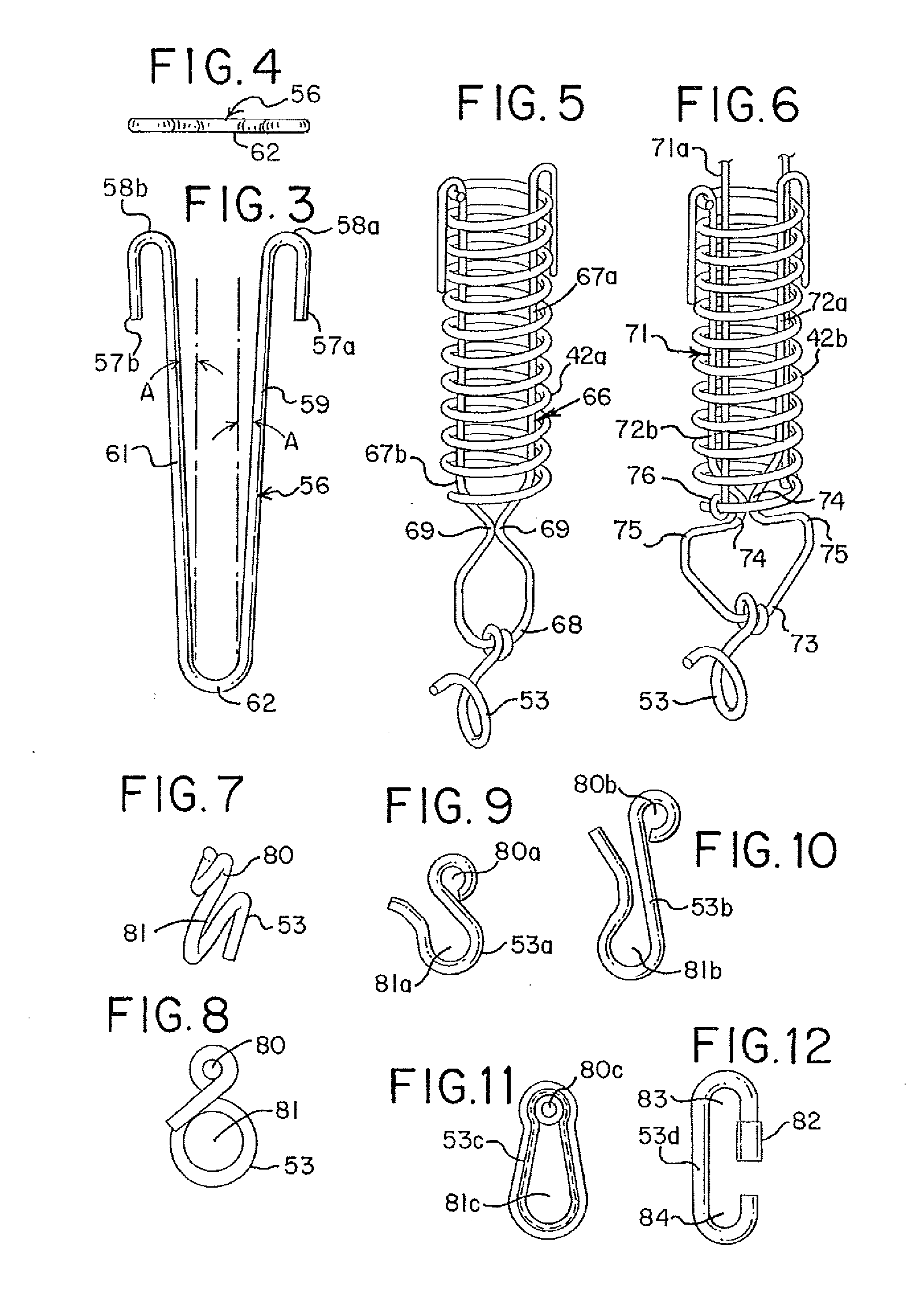
[0008]In achieving these types of functions of air brake hose supports, the present disclosure seeks to address an objective of having a very durable support assembly that still affords a reasonable degree of flexibility that is well controlled both during use as a hose assembly and upon disconnection of the hose coupling condition that is otherwise maintained during running of the train.
[0009]In one aspect of this disclosure, the air brake hose support of the present disclosure is fully metallic; that is, each component of the assembly is constructed of a durable metal. In addition, the air brake hose support is responsive to loads being applied to the assembly to the extent that the total length of the assembly increases under load while returning to its pre-loaded length, or within allowable limits of its pre-loaded length when the load is reduced or removed. A compressible spring defining an elongated passageway has received therewithin at least one spring wireform which contributes to action that compresses the compressible spring, resulting in elongation of the length of the support assembly.
[0010]In another aspect of this disclosure, a railway air brake hose support is provided to include a longitudinally compressible coil spring. A first spring wireform is positioned at least partially within the compressible spring and has at least two legs that engage one end portion of the longitudinally compressible spring, with the other end of the spring wireform being within or projecting beyond the other end of the compressible coil spring. A second internal spring wireform is similarly positioned with respect to the compressible coil spring, except its legs engage the other end portion of the compressible spring while being within or protruding from the end of the compressible spring at which the first internal spring wireform is engaged. The first such other end of the first internal spring wireform is attached, directly or indirectly, to a coupler of the railway car, while the second such other end is attached, directly or indirectly, to the air brake hose, typically at its glad hand location. When forces are encountered along the assembly, the wireforms are able to move in opposite directions in opposition to the bias of the longitudinally compressible spring, allowing for length extension of the support assembly and substantially full reversal on that extension upon removal or dissipation of such force.
[0014]In an added aspect of this disclosure, a railway air brake hose support is provided to include a longitudinally compressible coil spring. A first spring wireform is positioned within the compressible spring and has at least two legs that engage one end portion of the longitudinally compressible spring, with the other end of the spring wireform projecting beyond the other end of the compressible coil spring. A second internal spring wireform is similarly positioned with respect to the compressible coil spring, except its legs engage the other end portion of the compressible spring while protruding from the end of the compressible spring at which the first internal spring wireform is engaged. The end of the first internal spring wireform that projects beyond the compressible coil spring is attached, directly or indirectly, to a coupler of the railway car, while the portion of the second internal spring wireform that extends beyond the compressible coil spring is attached, directly or indirectly, to the air brake hose, typically at its glad hand location. When forces are encountered along the assembly, the wireforms are able to move in opposite directions in opposition to the bias of the longitudinally compressible spring, allowing for length extension of the support assembly and substantially full reversal on that extension upon removal or dissipation of such force such that the unit exhibits a spring set of not greater than 0.5 inch.
[0015]In a further aspect of this disclosure, a railway hose support assembly is provided with a retraction-biased extension unit having a longitudinally compressible spring having a first end, a second end, and an inside surface, as well as a first internal spring wireform positioned within the compressible spring inside surface having at least two legs meeting at a closed end to define a biased outwardly angle of at least one of the legs of at least 0.5 angular degree to enhance damping, each leg having a free end spaced away from the closed end, each free end securely engaging the longitudinally compressible spring first end, together with a second internal spring wireform positioned within the compressible spring inside surface having at least two legs meeting at a closed end, each leg having a free end spaced away from the closed end, each free end securely engaging the longitudinally compressible spring second end. The closed end of each of the first and second internal spring wireforms is accessible externally of the longitudinally compressible spring, whereby movement of the respective closed ends in opposite directions compresses the longitudinally compressible spring when a load is applied between a railway brake hose and a railway coupler. The closed ends of the respective internal spring wireforms are adapted to securely engage with a railway brake hose glad hand aperture and a railway coupler aperture.

Problems solved by technology

It will be appreciated that uncoupling by air brake hoses along a railway train while in transport mode typically will cause emergency braking and perhaps excessively abrupt stopping of the train cars involved, which can lead to inconvenience and possible safety concerns.
Damage to equipment and even derailment can be included in these concerns.

Method used


Image

  • Spring-style air brake hose support
  • Spring-style air brake hose support
  • Spring-style air brake hose support

Examples


Embodiment Construction

[0047]As required, detailed embodiments of the present invention are disclosed herein; however, it is to be understood that the disclosed embodiments are merely exemplary of the invention, which may be embodied in various forms. Therefore, specific details disclosed herein are not to be interpreted as limiting, but merely as a basis for the claims and as a representative basis for teaching one skilled in the art to variously employ the present invention in virtually any appropriate manner.

[0048]FIG. 1 and FIG. 2 illustrate an embodiment of a railway hose support, generally designated at 31, which includes a plurality of components connected to and engaged with each other. Support assembly 31 is illustrated in its in-use condition by which a railway hose 32, such as an air brake hose or steam hose, is suspended at its glad hand end 33 from a railway coupler 34. More particularly, one of the components of the support assembly is inserted through an orifice of a coupler bracket 35. The...


PUM


Abstract

A spring-style railway hose support has a retraction-biased extension unit of a longitudinally compressible spring and a pair of oppositely directed internal wireforms within the longitudinally compressible spring. The internal wireforms engage respective ends of the longitudinally compressible spring, and a closed end of each is configured to allow it to project beyond a respective end of the longitudinally compressible spring. The retraction-biased extension unit is adapted to be directly or indirectly connected to a railway brake hose and to a railway car component that is positioned above the hose on a railway car.

Description

BACKGROUND[0001]1. Field of the Disclosure[0002]The present subject matter relates to supports for railway hoses, and particularly to support assemblies that are of a spring style and provide both stretch and energy absorption during use in suspending and supporting railway brake air hoses, typically from a hose glad hand to a railway coupler.[0003]2. Description of Related Art[0004]Suspension devices for air brake hoses of railway cars are known for suspending from railway car couplers. Such suspension devices help to safely maintain a hose in place during use and transport while allowing for limited movement of the air brake hose in order to facilitate connection of the air brake hose to the remainder of the air brake mechanism and line while permitting the air brake hose to move as needed in order to avoid undesired uncoupling while still restricting movement of the hose to an extent that uncoupling is accomplished only when desired. A typical function of such devices is to provi...

Claims


Application Information

Patent Timeline
Patent Type & Authority Applications(United States)
IPC IPC(8): B60T17/04F16L3/14F16F1/04
CPCB60T17/046F16L3/14F16F1/04B61G5/08F16L3/2053F16F1/128F16F2236/04Y10T24/312F16L3/01F16L55/005B61G5/06B60D1/62F16L3/003B60T17/043B61G7/02
Inventor MAKI, BRIAN G.
Owner IRECO INC
Why Eureka
Try Eureka