Eureka AIR delivers breakthrough ideas for toughest innovation challenges, trusted by R&D personnel around the world.

Tire Manipulation System

a technology of manipulators and tires, which is applied in the direction of wheel mounting apparatus, manufacturing tools, instruments, etc., can solve the problems of cumbersome tire handling, time-consuming and expensive to change/repair a damaged tire on a vehicle, and tire problems that are difficult to remove from a vehicl

Active Publication Date: 2015-06-04
JOGGER IND LLC
View PDF18 Cites 15 Cited by
  • Summary
  • Abstract
  • Description
  • Claims
  • Application Information

AI Technical Summary

Benefits of technology

The invention is a tire manipulator that can be attached to a tractor and used to engage and manipulate tires. It includes a mounting device, a telescoping main support structure, a main actuator, a pivot axle, a support frame, and a pair of telescoping supports with actuators and gripping members. The gripping members first engage the perimeter of a tire and then the user can manipulate the tire's attitude using the loader system of the tractor. The invention allows for easy and efficient manipulation of tires.

Problems solved by technology

Tires for vehicles can be difficult to remove from a vehicle, move to a different location and install on a vehicle because of their weight and size.
In addition, the tires may have a large diameter of 6 feet or more making it difficult for workers to handle the cumbersome tire.
Because of the significant manual labor involved in manipulating large tires, it is very time consuming and expensive to change / repair a damaged tire on a vehicle.

Method used


Image

  • Tire Manipulation System
  • Tire Manipulation System
  • Tire Manipulation System

Examples


Embodiment Construction

[0029]A. Overview.

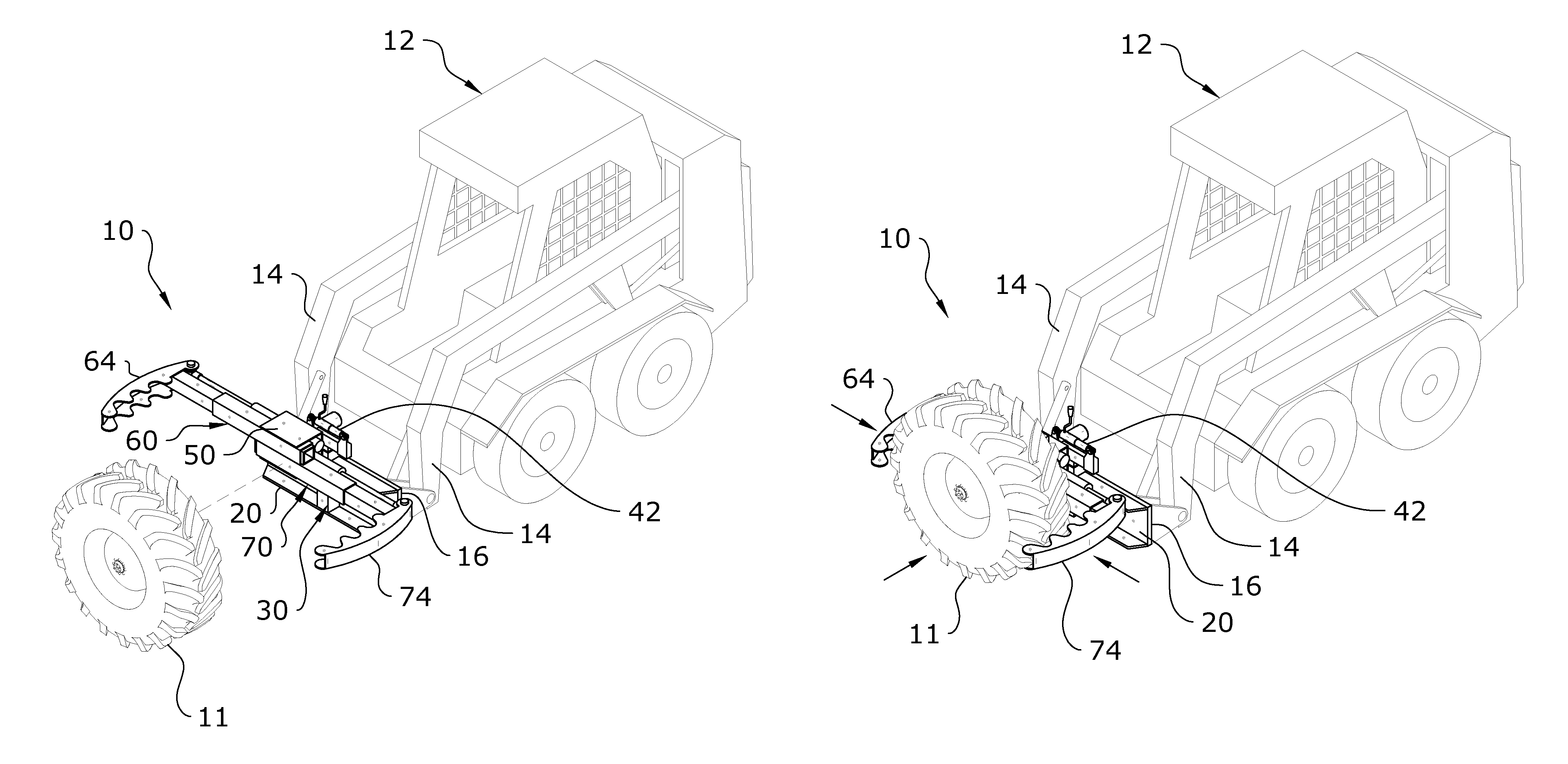
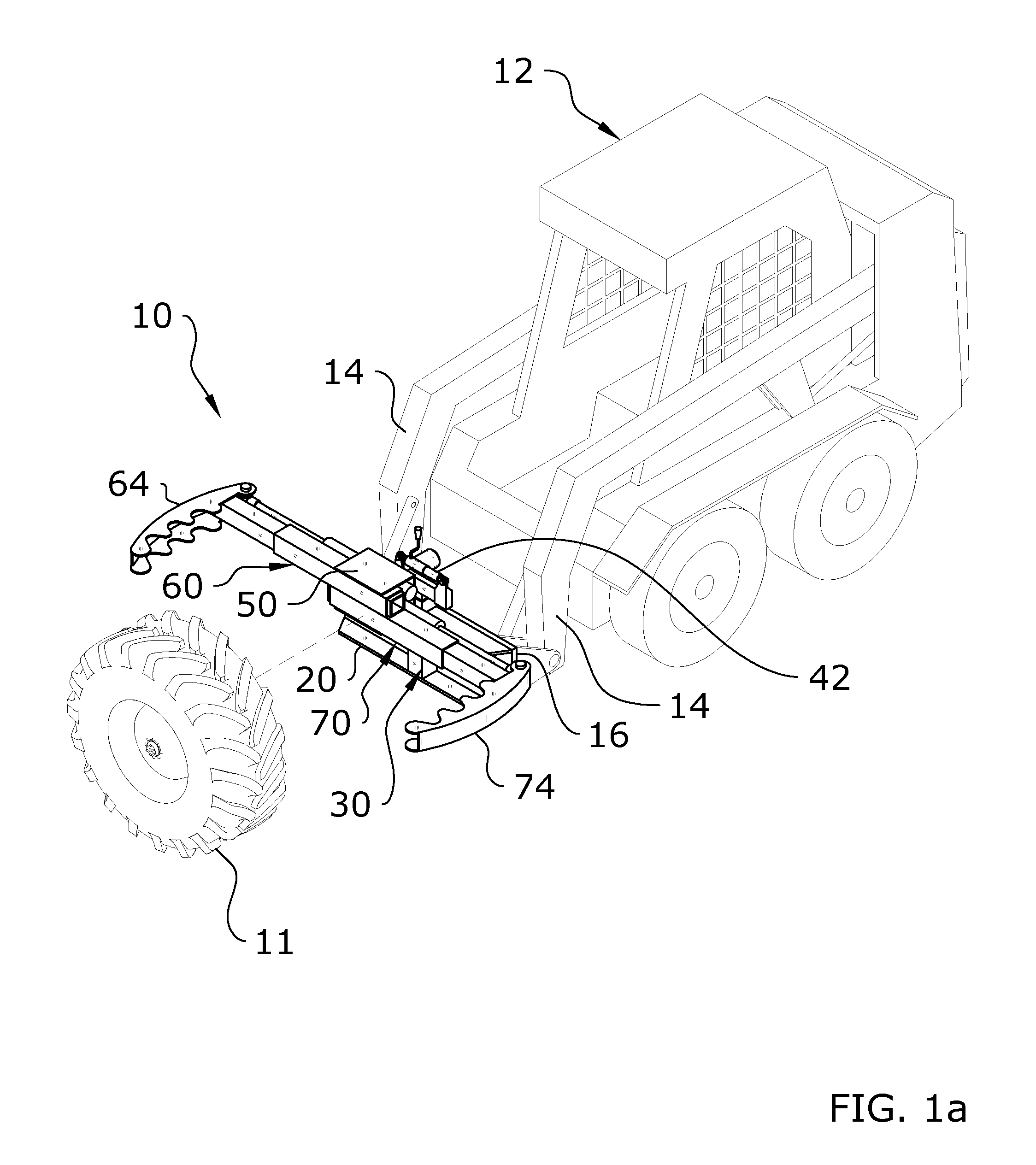
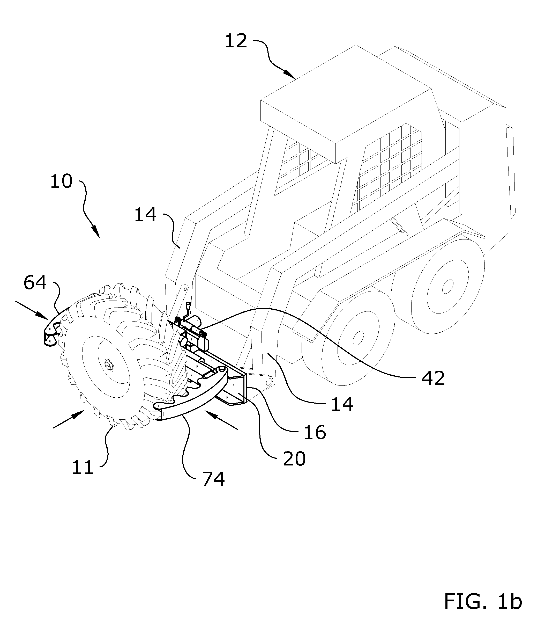
[0030]Turning now descriptively to the drawings, in which similar reference characters denote similar elements throughout the several views, FIGS. 1 through 13 illustrate a tire manipulation system 10, which comprises a mounting device 20 for removable attachment to a tractor 12, a telescoping main support structure 30 attached to the mounting device 20, a main actuator 38 connected to the main support structure 30, a pivot axle 40 rotatably connected to the main support structure 30, a support frame 50 connected to the pivot axle 40, and a pair of telescoping supports each having an actuator and a gripping member for engaging a tire 11 to be manipulated. The gripping members 64, 74 first engage the perimeter of a tire 11 to be manipulated and then using the loader system of the tractor 12 the user is able to manipulate the attitude of the tire 11.

[0031]The present invention may be attached to various types of tractors 12 including, but not limited to, skid steer t...


PUM


Abstract

A tire manipulation system for efficiently manipulating the position of a tire. The tire manipulation system generally includes a mounting device for removable attachment to a tractor, a telescoping main support structure attached to the mounting device, a main actuator connected to the main support structure, a pivot axle rotatably connected to the main support structure, a support frame connected to the pivot axle, and a pair of telescoping supports each having an actuator and a gripping member for engaging a tire to be manipulated. The gripping members first engage the perimeter of a tire to be manipulated and then using the loader system of the tractor the user is able to manipulate the attitude of the tire.

Description

CROSS REFERENCE TO RELATED APPLICATIONS[0001]Not applicable to this application.STATEMENT REGARDING FEDERALLY SPONSORED RESEARCH OR DEVELOPMENT[0002]Not applicable to this application.BACKGROUND OF THE INVENTION[0003]1. Field of the Invention[0004]The present invention relates generally to a tire manipulator and more specifically it relates to a tire manipulation system for efficiently manipulating the position of a tire.[0005]2. Description of the Related Art[0006]Any discussion of the related art throughout the specification should in no way be considered as an admission that such related art is widely known or forms part of common general knowledge in the field.[0007]Tires for vehicles can be difficult to remove from a vehicle, move to a different location and install on a vehicle because of their weight and size. For example, two or more workers are typically required to remove, move and install a tire for a tractor which can easily weigh 500 pounds or more. In addition, the tir...

Claims


Application Information

Patent Timeline
IPC IPC(8): B60B29/00B60B30/02
CPCB60B30/02B60B29/001B60B29/002Y10S414/124
Inventor GRENGS, GREG L.
Owner JOGGER IND LLC
Why Eureka
Eureka Blog
Learn More