
Cryogenically cooled radiation shield device and associated method

a radiation shield and cryogen cooling technology, applied in the field of methods and devices, can solve the problems of human cells being damaged by radiation exposure, sensitive electronic components and other devices being adversely affected, and the use of radiation absorption materials being unpractical for space exploration and other applications, and achieve the effect of less cryogen liquid consumption

Inactive Publication Date: 2015-05-28
THE BOEING CO
View PDF17 Cites 3 Cited by
  • Summary
  • Abstract
  • Description
  • Claims
  • Application Information

AI Technical Summary

Benefits of technology

[0008]A cryogenically cooled radiation shield device as well as an associated method are provided according to embodiments of the present disclosure in order to shield an area, such as the capsule of a space vehicle, from radiation, such as the charged particles released during CMEs. In this regard, the cryogenically cooled radiation shield device and associated method of one embodiment are configured to deflect the particles of radiation in a manner that is lighter and / or consumes less cryogen liquid than some prior approaches.
[0014]In one embodiment, the at least one first coil may be pre-cooled prior to commencement of the mission, thereby reducing the quantity of cryogen liquid that must be carried during the mission. The first cryogen liquid may have a lower boiling point than the second cryogen liquid. For example, the first cryogen liquid may be liquid helium, and the second cryogen liquid may be liquid oxygen, liquid nitrogen, or liquid hydrogen. In one embodiment, the circulation of a second cryogen liquid may include the sequential circulation of a plurality of different cryogen liquids through the second conduit. In this embodiment, the plurality of different cryogen liquids may be sequentially circulated through the second conduit in order of descending boiling point. Accordingly, the circulation of the first cryogen liquid through the first conduit may commence following the sequential circulation of a plurality of different cryogen liquids through the second conduit.

Problems solved by technology

Such proton and heavy ion radiation can cause cell damage to humans exposed to such radiation.
Additionally, sensitive electronic components and other devices may be adversely affected by such radiation.
However, because of the significant amount of weight such a housing would require, the use of radiation absorbing material is not practical for space exploration and other applications.
Additionally, the absorption of high energy particles may release a different form of radiation such as gamma rays and X-rays that pass through the shielding material and create other difficulties for the crew and / or equipment.
However, the electrical refrigeration units may be relatively heavy and may consume a substantial amount of electrical power.
In addition, the electrical refrigeration unit may require electrical power generation and distribution, which also disadvantageously adds to the overall weight of the system.
As it is often desirable to reduce the weight of a spacecraft, it may therefore be undesirable to include an electrical refrigeration unit and the associated electrical power generation distribution system in order to cool the coils formed of a superconducting material to a temperature near absolute zero.
Since the latent heat of the liquid helium is relatively low, however, an excessive amount of liquid helium, as measured in terms of the weight and volume of the liquid helium, may need to be boiled off in order to cool the coils.
As such, a substantial quantity of liquid helium may be required to be provided in order to sufficiently cool the coils formed of a superconductive material, thereby disadvantageously increasing the weight of the spacecraft or the like.

Method used


Image

  • Cryogenically cooled radiation shield device and associated method
  • Cryogenically cooled radiation shield device and associated method
  • Cryogenically cooled radiation shield device and associated method

Examples


Embodiment Construction

[0025]Embodiments of the present disclosure now will be described more fully hereinafter with reference to the accompanying drawings, in which some, but not all embodiments are shown. Indeed, these embodiments may be embodied in many different forms and should not be construed as limited to the embodiments set forth herein; rather, these embodiments are provided so that this disclosure will satisfy applicable legal requirements. Like numbers refer to like elements throughout.

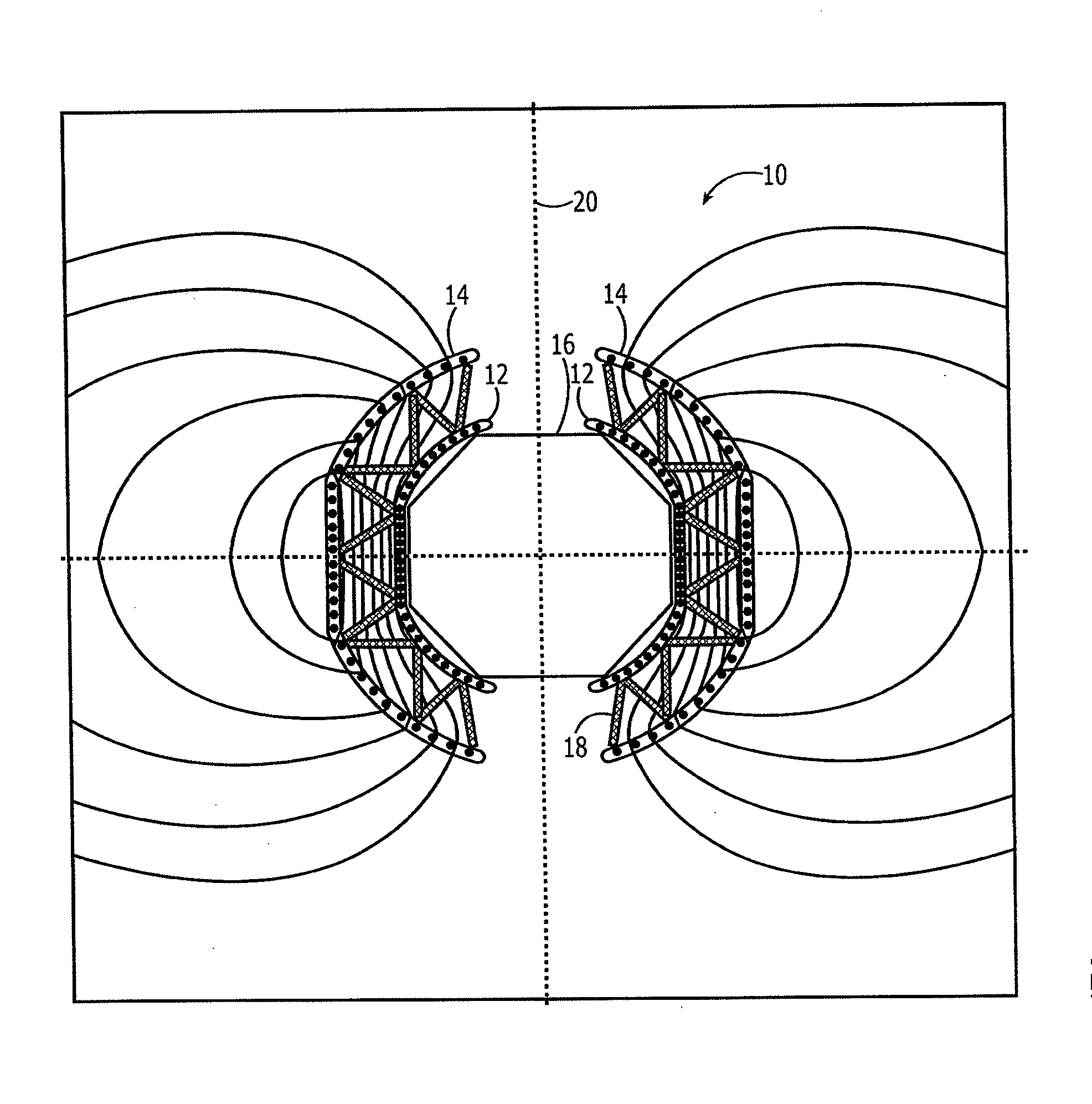
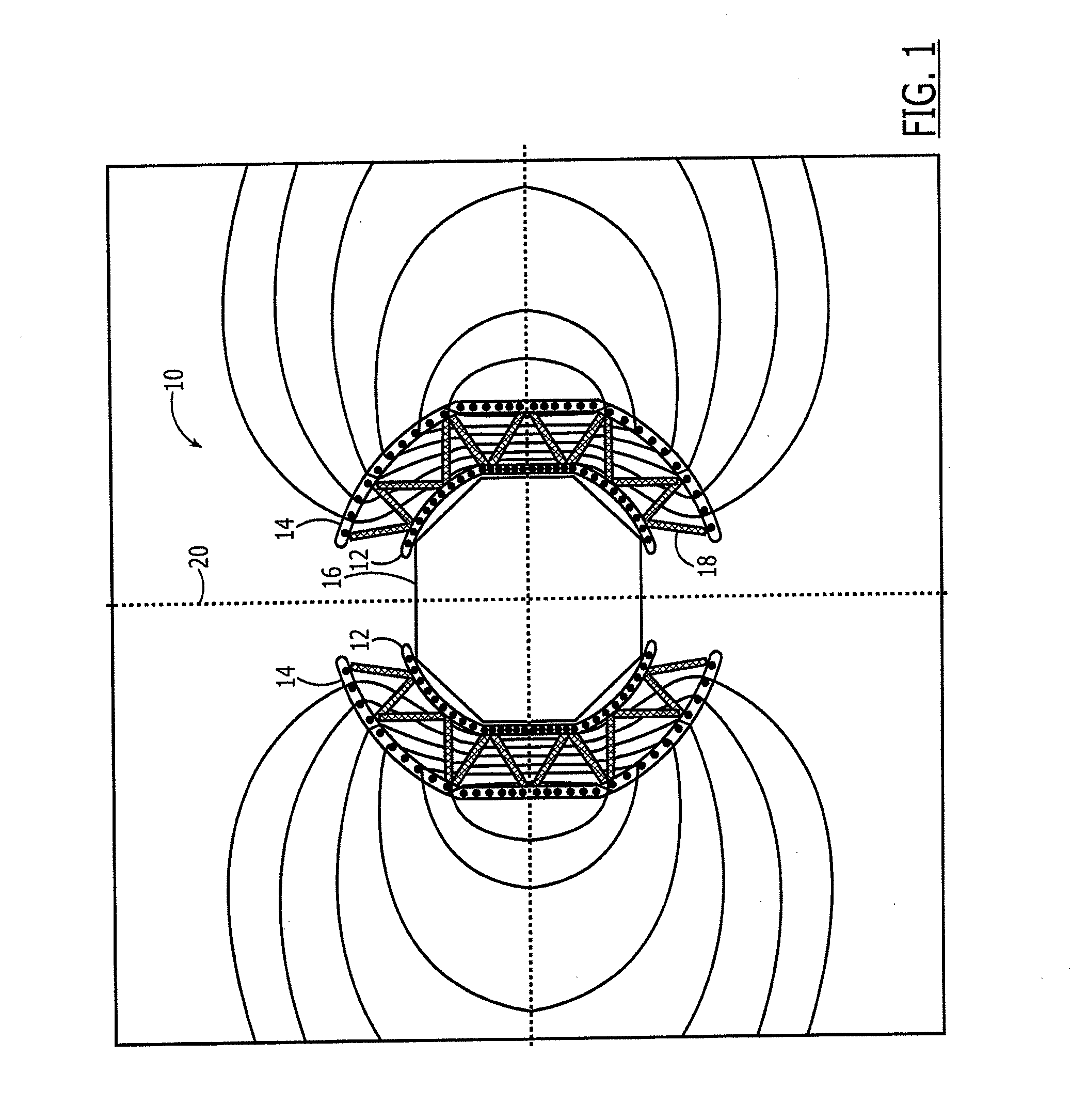
[0026]Referring now to FIG. 1, the radiation shield device 10 in accordance with one embodiment of the present disclosure is illustrated. The radiation shield device 10 is generally described herein as providing protection from radiation for a manned space vehicle or a habitat for celestial bodies, particularly during CME events. However, further embodiments of the present disclosure may include radiation shield devices for any situation in which protection from particle radiation is desired beyond the earth's m...


PUM


Abstract

A cryogenically cooled radiation shield device and method are provided to shield an area, such as the capsule of a space vehicle, from radiation. A cryogenically cooled radiation shield device may include at least one first coil comprised of a superconducting material extending about an area to be shielded from radiation. The cryogenically cooled radiation shield device also includes a first conduit extending about the area to be shielded from radiation. The at least one first coil is disposed within the first conduit. The cryogenically cooled radiation shield device also includes a second conduit extending about the area to be shielded from radiation. The first conduit is disposed within the second conduit. The cryogenically cooled radiation shield device also includes a first cryogen liquid disposed within the first conduit and a second cryogen liquid, different than the first cryogen liquid, disposed within the second conduit exterior of the first conduit.

Description

CROSS REFERENCE TO RELATED APPLICATIONS[0001]This application is a divisional of and claims priority to U.S. application Ser. No. 12 / 966,350, filed Dec. 13, 2010, which is a continuation-in-part of U.S. application Ser. No. 12 / 966,315, filed Dec. 13, 2010, the entire contents of each are hereby incorporated by reference.TECHNOLOGICAL FIELD[0002]Embodiments of the present disclosure relate generally to methods and devices for shielding an area from radiation and, more particularly, to a cryogenically cooled radiation shield device and an associated method.BACKGROUND[0003]The sun occasionally releases significant amounts of charged particles during events known as coronal mass eject as (“CMEs”). The charged particles released during CMEs include electrons, protons, and heavy ions. Each CME may last for about one or two days in the vicinity of earth, but their effects may linger for up to a week. Such proton and heavy ion radiation can cause cell damage to humans exposed to such radiat...

Claims


Application Information

Patent Timeline
Patent Type & Authority Applications(United States)
IPC IPC(8): B64G1/58B64G1/54
CPCB64G1/54B64G1/58G21F1/00G21F3/00B64G1/50
Inventor KINSTLER, GARY A.
Owner THE BOEING CO
Learn More