
Hinge for an orthopedic brace

Active Publication Date: 2015-05-21
PLUS MEDITECH
View PDF6 Cites 16 Cited by
  • Summary
  • Abstract
  • Description
  • Claims
  • Application Information

AI Technical Summary

Benefits of technology

The present invention aims to provide a hinge for orthopedic brace that can overcome the shortcomings of the prior art.

Problems solved by technology

In addition, since the leaf spring is in contact with the pivotal connector, rotation of the leaf spring about the pivotal connector may cause wear type damage to the leaf spring and / or the pivotal connector.

Method used


Image

  • Hinge for an orthopedic brace
  • Hinge for an orthopedic brace
  • Hinge for an orthopedic brace

Examples


Embodiment Construction

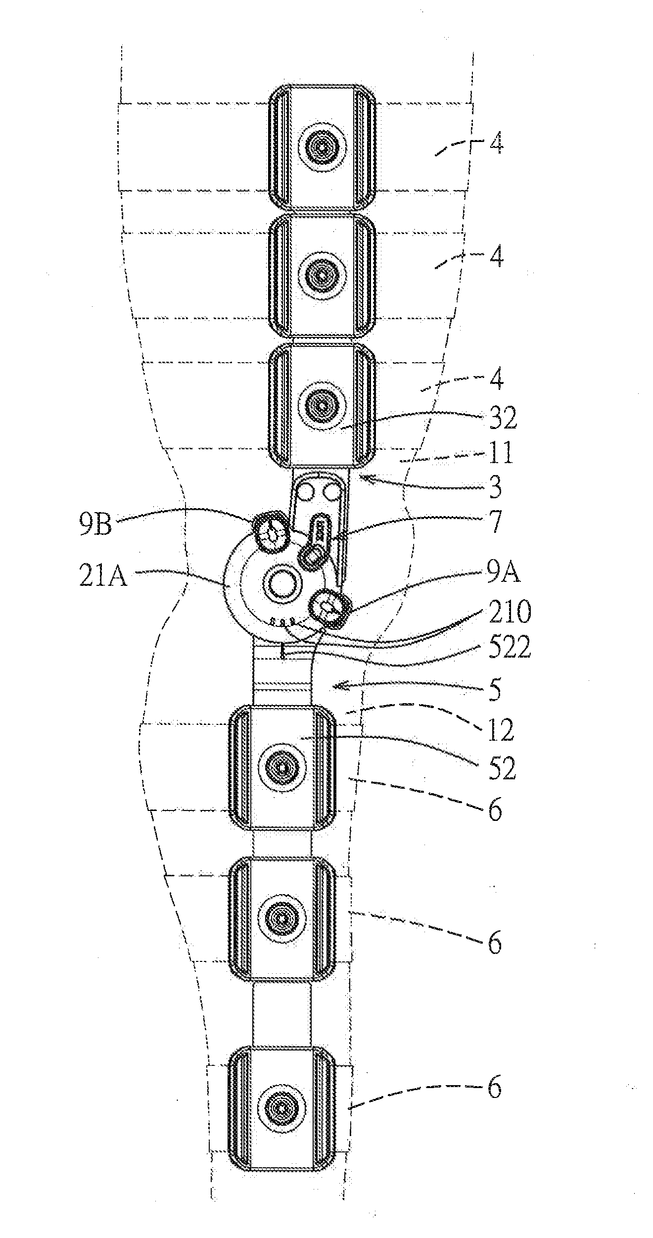
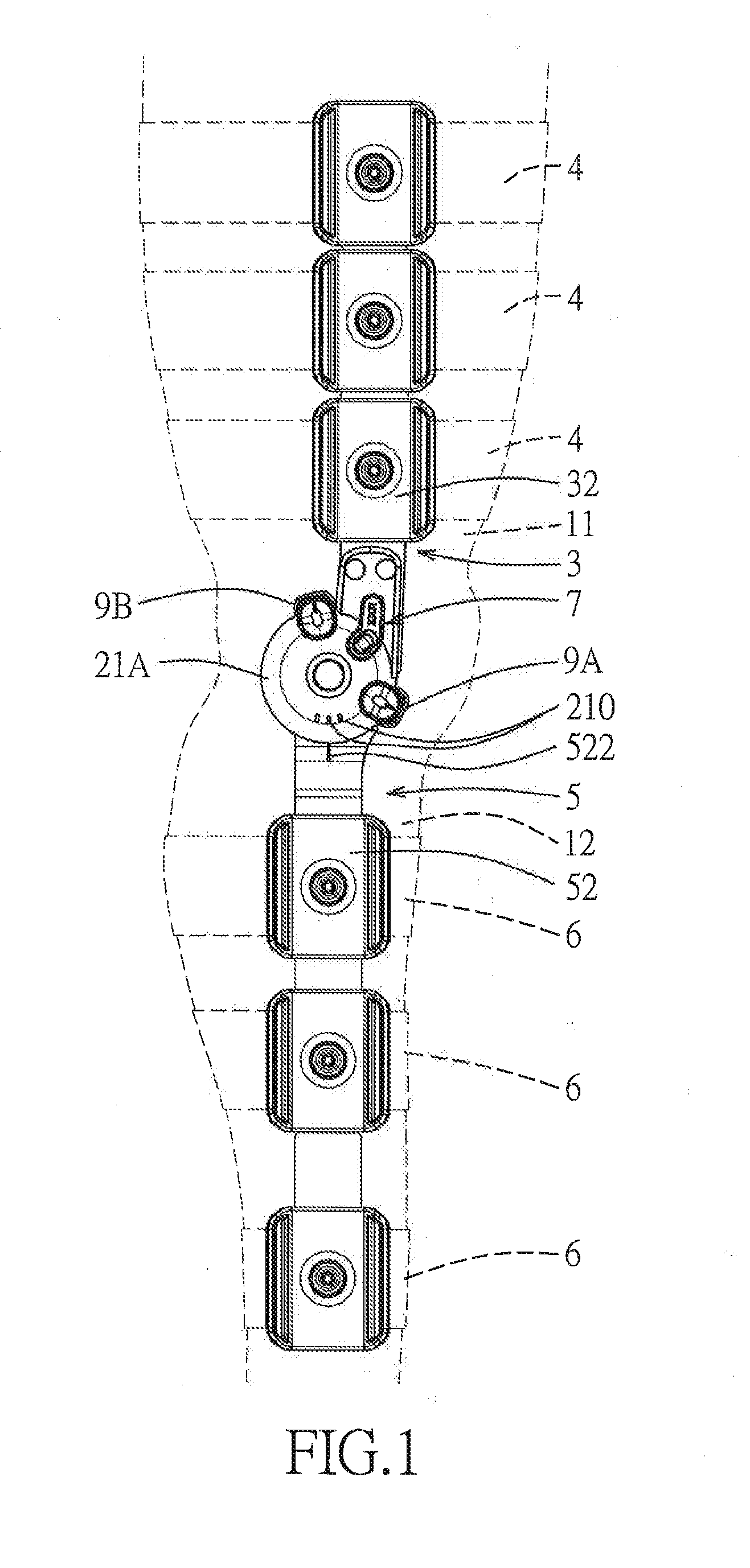
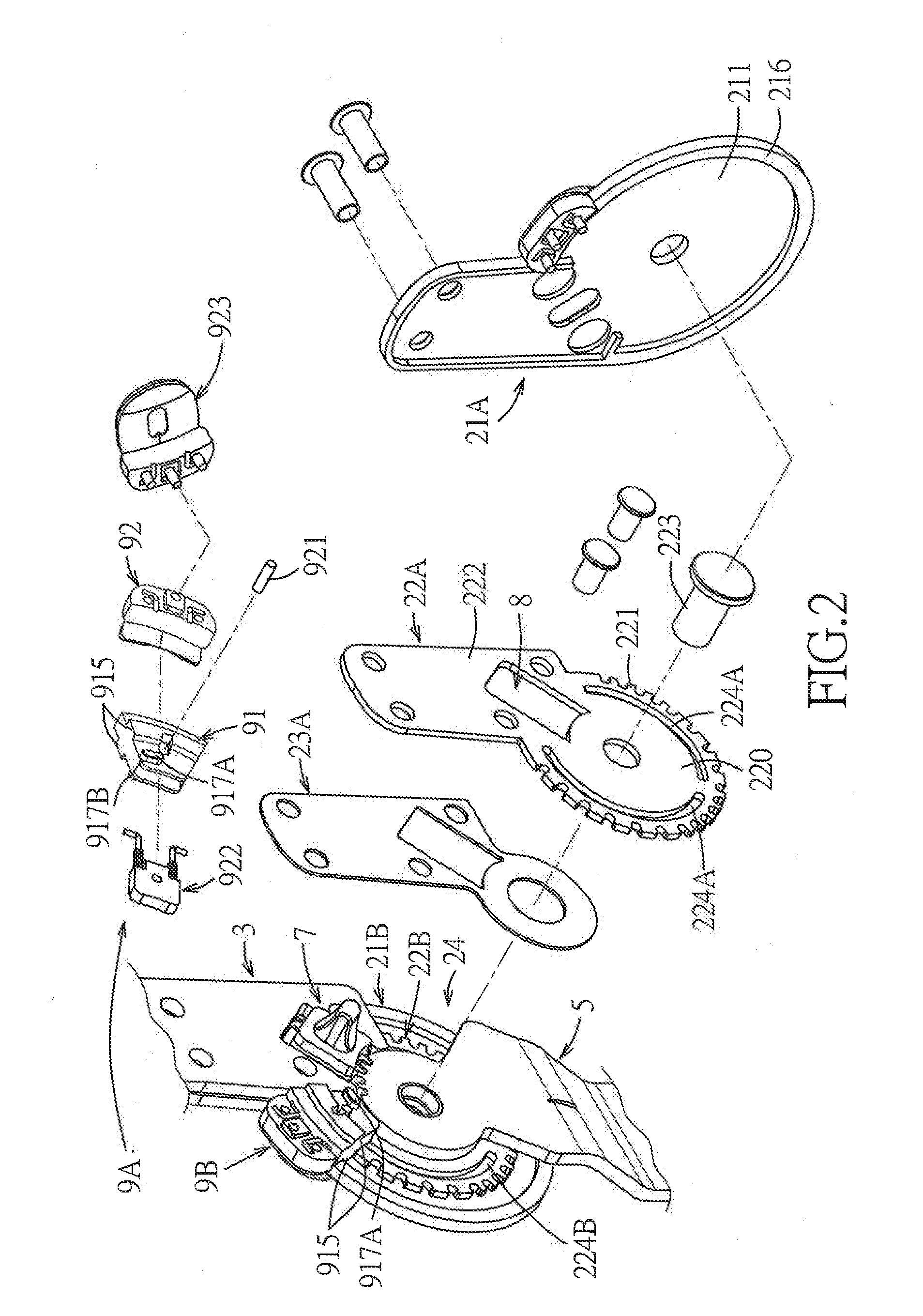
[0024]FIGS. 1 to 8 illustrate the preferred embodiment of a hinge for an orthopedic brace according to the present invention. The orthopedic brace includes a plurality of upper wearing bands 4 and a plurality of lower wearing bands 6. The hinge includes a pivot shaft 223, upper and lower leg plates 3, 5, first and second covers 21A, 21B, first and second catch plates 22A, 22B, first and second buffering pads 23A, 23B, first and second position adjusting units 9A, 9B, and a lock mechanism 7.

[0025]Each of the first and second catch plates 22A, 22B has an annular portion 220, and a securing fin portion 222 that extends from the annular portion 220 and that is secured to an end portion 31 of the upper leg plate 3 through fastening means. The annular portion 220 is sleeved around the pivot shaft 223, and has a toothed peripheral edge 221. The annular portions 220 of the first and second catch plates 22A, 22B are coaxially disposed, and cooperate with each other to define an insertion gap...


PUM


Abstract

A hinge for an orthopedic brace includes: a pivot shaft; a lower leg plate pivoted to the pivot shaft; an upper leg plate; a catch plate having a toothed peripheral edge; and two position adjusting units, each of which includes a rotatable limiting seat, a limiting pin, and a slider body. The rotatable limiting seat defines a housing chamber therein, and is formed with a wall slot. The slider body is slidably disposed in the housing chamber. The limiting pin extends from the slider body through the wall slot for engaging and disengaging the toothed peripheral edge. The catch plate is formed with a guiding groove. The rotatable limiting seat has a tongue protruding into the guiding groove.

Description

CROSS-REFERENCE TO RELATED APPLICATION[0001]This application claims priority of Taiwanese Application No. 102142046, filed on Nov. 19, 2013.BACKGROUND OF THE INVENTION[0002]1. Field of the Invention[0003]This invention relates to a hinge for an orthopedic brace, more particularly to a hinge for an orthopedic brace including a rotatable limiting seat and a slider body mounted in the limiting seat.[0004]2. Description of the Related Art[0005]U.S. Pat. No. 7,235,059 discloses a conventional hinge for an orthopedic brace. The conventional hinge includes upper and lower arms, first and second rotation plates, a pivotal connector connecting the first and second rotation plates, and a rotation limiting mechanism for limiting an angle between the first and second rotation plates. The rotation limiting mechanism includes a series of rotation limiting teeth that are formed on peripheral edges of the first and second rotation plates, a flexion rotation limiting assembly, and an extension rotat...

Claims


Application Information

Patent Timeline
IPC IPC(8): A61F5/01
CPCA61F5/0123A61F2005/0181A61F2005/0165A61F2005/0137A61F5/0125A61F2005/0158A61F2005/0167
Inventor CHIANG, YUEH-HUACHUANG, FU-LIN
Owner PLUS MEDITECH
Learn More