
Pressure reducer for supplying drugs to a patient and corresponding production method

a technology of pressure reducer and drug delivery, which is applied in the direction of flow monitor, lamination, domestic articles, etc., can solve the problems of increasing the pressure loss of the pressure reducer, and achieve the effect of easy welding seams

Active Publication Date: 2015-05-14
LEVENTON
View PDF5 Cites 0 Cited by
  • Summary
  • Abstract
  • Description
  • Claims
  • Application Information

AI Technical Summary

Benefits of technology

The invention is a pressure reducer that has a unique design to overcome the problems of existing pressure reducers. The reducer has two bodies that directly contact each other, forming a duct between their surfaces. The two bodies are attached to each other by a continuous attachment line that runs from the inlet to the outlet. This eliminates the need for intermediate joints and ensures accurate pressure reduction. The second body is a rigid sheet made by die cutting a prefabricated sheet. The thickness of the sheet is preferably between 20 and 500 microns, and it can be easily laser welded onto the first body. The invention provides a more efficient and reliable pressure reducer that is cost-effective and easy to manufacture.

Problems solved by technology

This results in the pressure loss of the pressure reducer varying overtime (increasing).

Method used


Image

  • Pressure reducer for supplying drugs to a patient and corresponding production method
  • Pressure reducer for supplying drugs to a patient and corresponding production method
  • Pressure reducer for supplying drugs to a patient and corresponding production method

Examples


Embodiment Construction

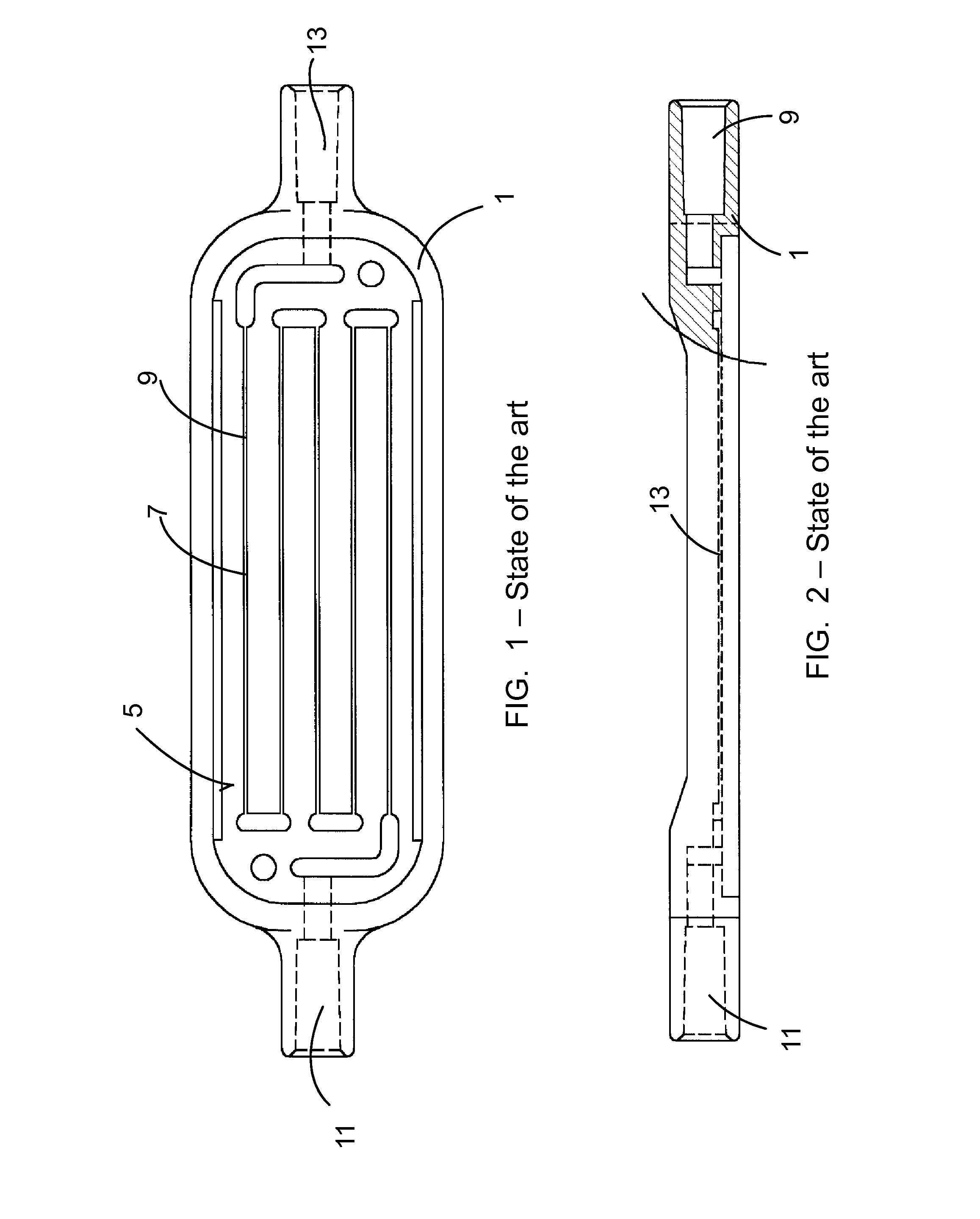
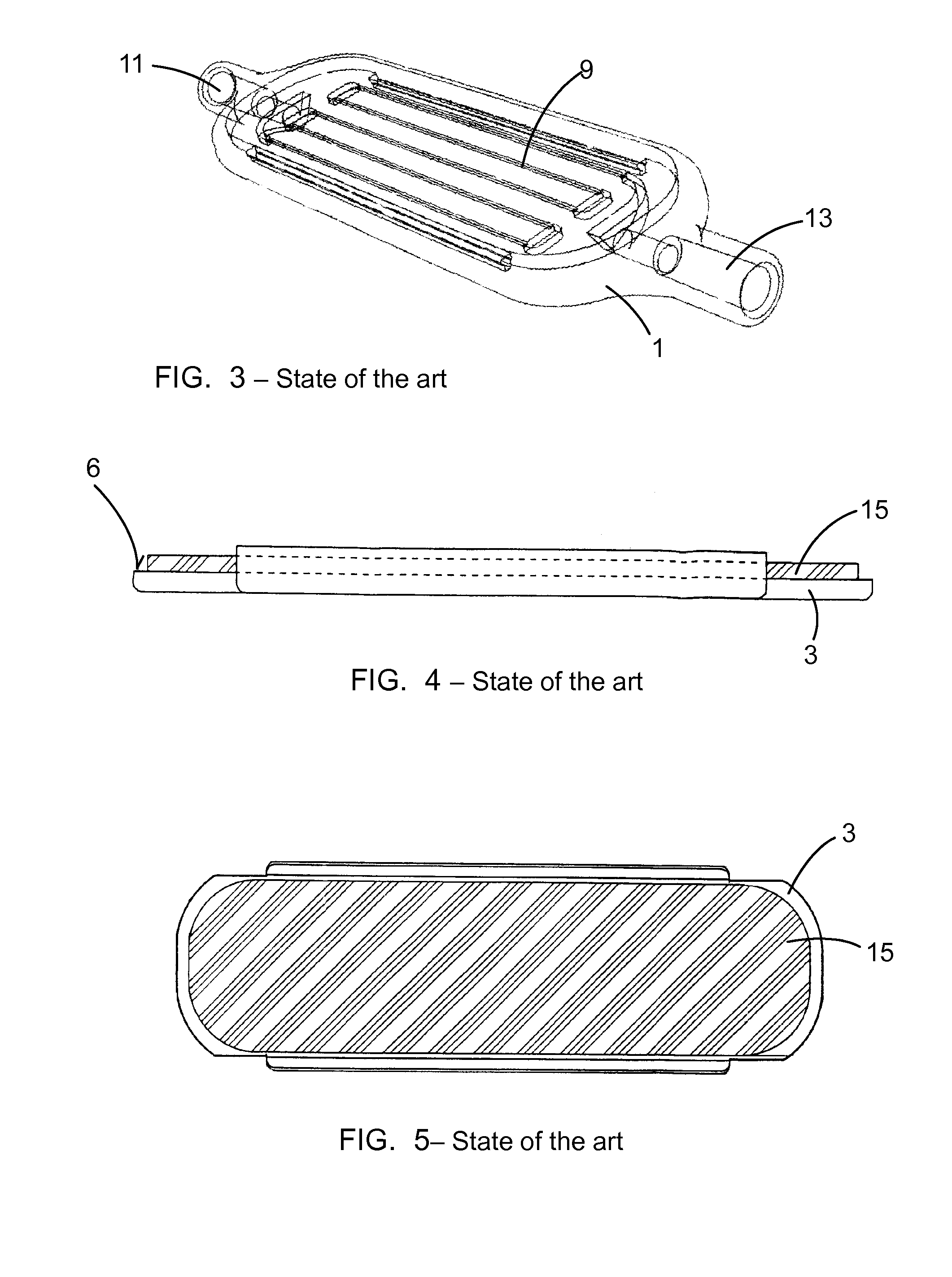
[0024]FIGS. 1 to 5 show a first body 1 and a second body 3 of a pressure reducer according to the state of the art, specifically as described in document WO 0241938, page 11, line 26 to page 13, line 8; FIGS. 1 to 7. The first body 1 has a first surface 5 in which there is a groove or recess 7 that will form the duct 9 extending from an inlet 11 to an outlet 13. The second body 3 in turn has a joint 15 injected on to a second surface 6. FIG. 6 shows both the first body 1 and the second body 3 assembled with one another, with the joint 15 forming the leak-tight closure. When the second body 3 is assembled on the first body 1, the joint 15 is partially introduced in the groove or recess 7, as shown in FIG. 7.

[0025]FIG. 8 shows another first body 1 of a pressure reducer according to the state of the art with a different geometric arrangement of the duct 9.

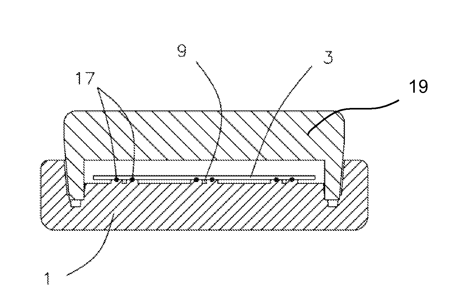
[0026]FIG. 9 shows a cross-section view of a pressure reducer according to the invention. The pressure reducer comprises a first bod...


PUM

PropertyMeasurementUnit
Thicknessaaaaaaaaaa
Thicknessaaaaaaaaaa
Thicknessaaaaaaaaaa

Abstract

The present invention relates to a pressure reducer for delivering drugs to a patient and the corresponding method of manufacture, said pressure reducer for delivering drugs to a patient comprising: a duct (9) with an inlet (11) and an outlet (13), a first body (1) with a first surface (5), and a second body (3) with a second surface (6) directly contacting the first body (1). One of the surfaces (5, 6) has a recess (7) such that a duct (9) is defined between both surfaces. Both bodies are attached to one another by means of a continuous attachment line running on both sides of the duct (9). The method of manufacture comprises a laser welding step in which the first body (1) is welded to the second body (3) by means of a welding seam extending along both sides of the duct.

Description

FIELD OF THE INVENTION [0001]The invention relates to a pressure reducer for delivering drugs to a patient, suitable for allowing the delivery of a certain fixed nominal flow rate of a drug, comprising: [a] a duct with an inlet and an outlet, where the duct is suitable for being traversed by the drug, [b] a first body with a first surface, and [c] a second body with a second surface, where the first body and the second body define an assembled position in which the first surface is substantially facing the second surface, and where at least one of the surfaces has at least one recess such that the duct is formed in the assembled position.[0002]The invention also relates to a method of manufacturing a pressure reducer of the mentioned type.STATE OF THE ART[0003]Pressure reducers of the type mentioned above are known. In various applications where it is necessary to deliver a drug to a patient through a blood vessel, devices delivering the drug for a more or less substantial period of...

Claims


Application Information

Patent Timeline
IPC IPC(8): A61M5/48A61M5/168B29C65/16A61M5/14
CPCA61M5/488A61M5/141A61M5/16804A61M2207/00A61M5/48B29C65/16A61M5/16877B29L2031/753B29C65/1616B29C65/1635B29C65/1654B29C66/112B29C66/114B29C66/244B29C66/5346B29C66/71B29C66/7352B29C66/919B29K2033/12
Inventor MARTIN LLORENS, JORDITORRAS MARI, JAVIER
Owner LEVENTON
Learn More