
Device for protecting the knee joint with a strap

a knee joint and strap technology, applied in the direction of protective garments, medical science, garments, etc., can solve the problems of complex structure, unfavorable knee joint protection, and ineffective co-operation with the knee joint for the purpose of protecting it, so as to improve the mechanical properties of the knee joint, improve the effect of stiffness and light weigh

Inactive Publication Date: 2015-04-23
GOUNIOT PIERRE
View PDF11 Cites 3 Cited by
  • Summary
  • Abstract
  • Description
  • Claims
  • Application Information

AI Technical Summary

Benefits of technology

The invention is a skis design that improves skiers' comfort while maintaining the ski's effectiveness in rotating around its Z axis. This is achieved by using a flexible material, such as foam or gel, as the lining of the ski. The shell and spacers are made of a rigid material, like magnesium, aluminum, or titanium, and can be in single-piece or composite form. Optionally, reinforcing materials like carbon fibers or glass fibers can be added to enhance the mechanical properties of the ski.

Problems solved by technology

However determining this trigger value for releasing the binding is itself problematic.
However the system disclosed is complex in structure and is clearly uncomfortable: the skier's lower limb is held on either side of the knee up to the thigh in a leg-brace that is hinged at knee level.
Its co-operation with the knee joint for the purpose of protecting it is also not very effective.
That device therefore does not enable forces applied to the device at knee level to be transferred to the boot, and to do so without impeding frontal flexion movements at knee level.

Method used


Image

  • Device for protecting the knee joint with a strap
  • Device for protecting the knee joint with a strap
  • Device for protecting the knee joint with a strap

Examples


Embodiment Construction

[0107]Unless otherwise specified in the present description, the term “leg” is used to designate the portion of a user's lower limb that is fitted with the device of the invention in register with the tibia bone. It is thus a zone extending under the knee towards the foot. In its portion situated above the knee, the bony structure of the lower limb comprises the femur, i.e. the thigh bone. At the knee, there is a kneecap. The tibia and the fibula are the bones of the leg. At its top end, the tibia has a joint via tibial plateaus to the bottom portion of the femur (femoral condyles).

[0108]FIG. 10 is a diagram of the invention. This figure shows the bottom of the body of a skier S. The skier S has a ski boot 2, which is fastened to a ski 1 by means of a binding 1a. The boot 2 has a footwear portion surmounted by a cuff 21. The foot P, the tibia T, and the femur F of the skier S can be seen. The femur F has condyles CF at its distal end. These condyles CF occupy a plurality of intermed...


PUM


Abstract

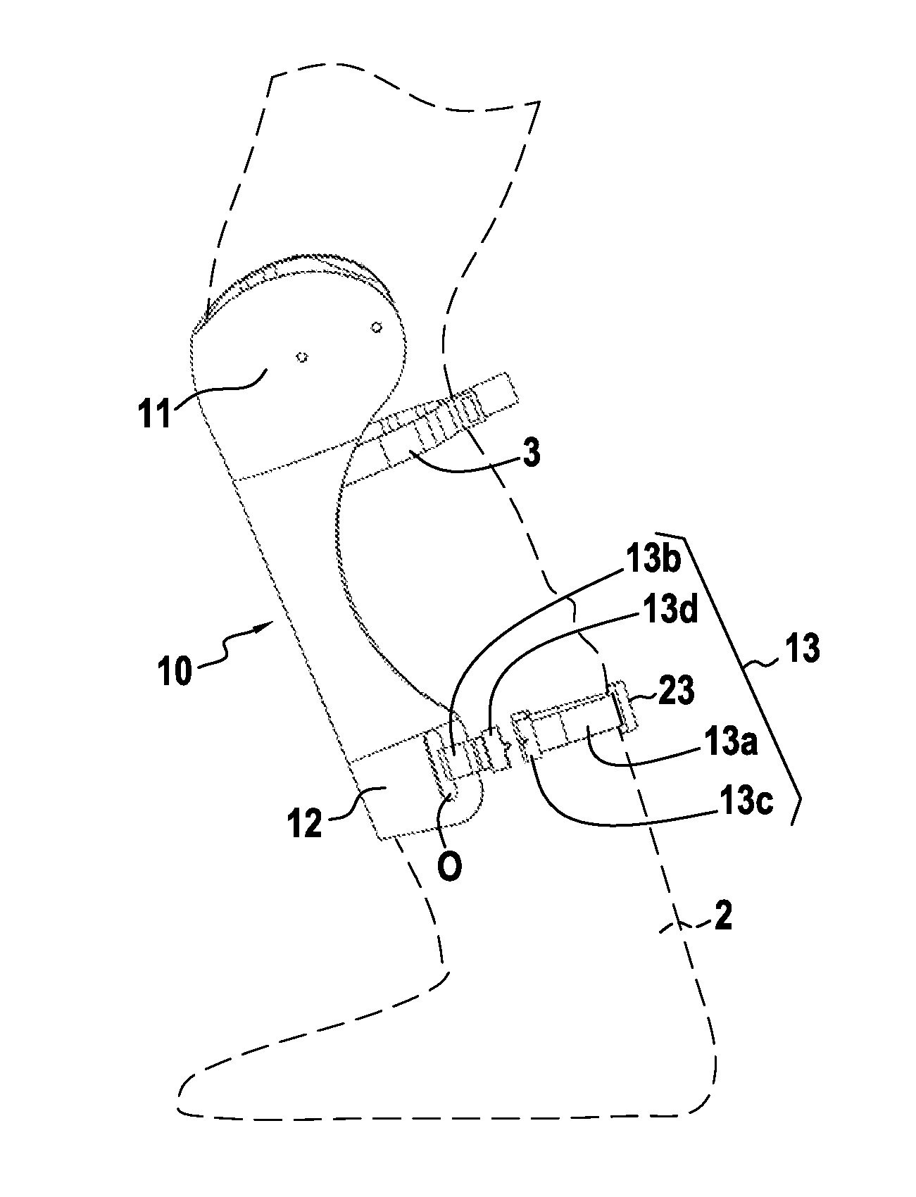
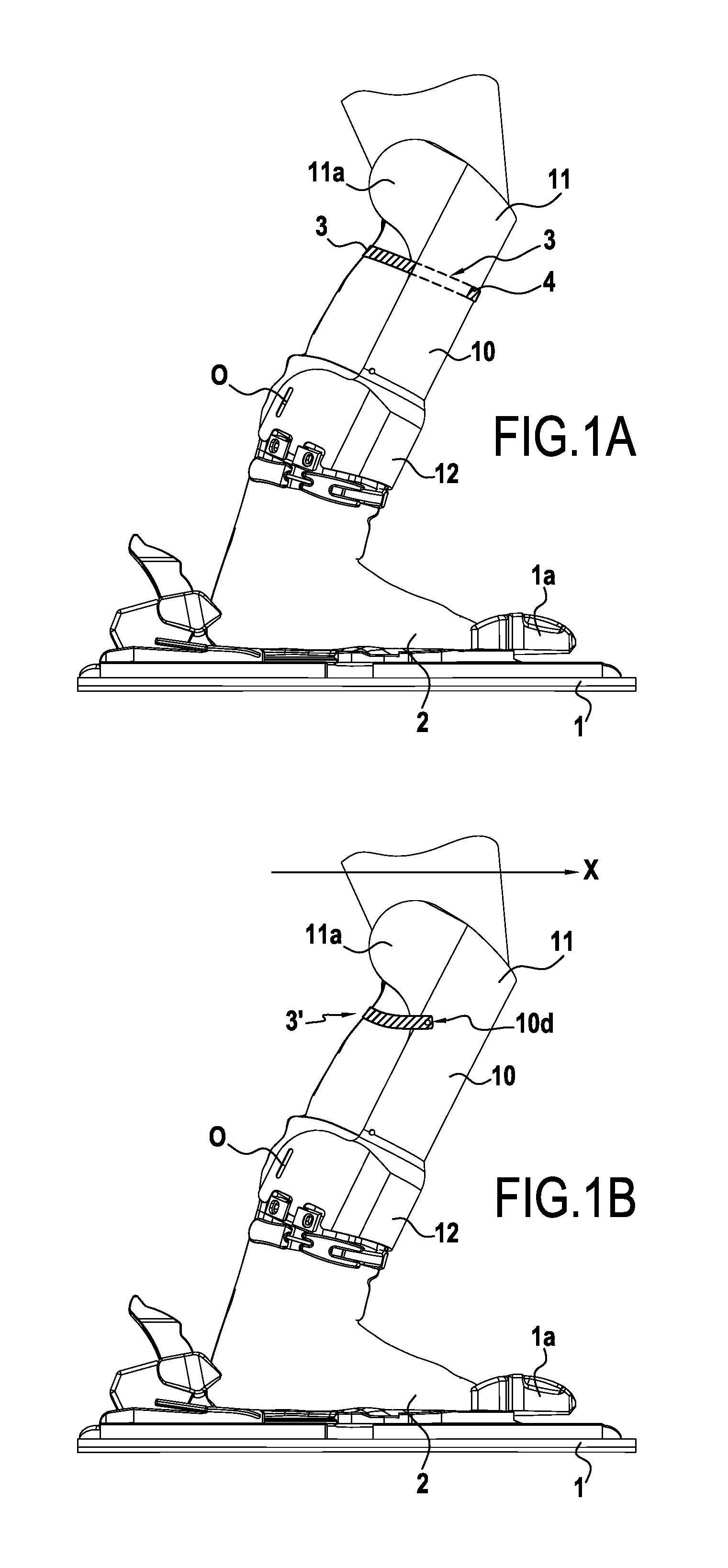
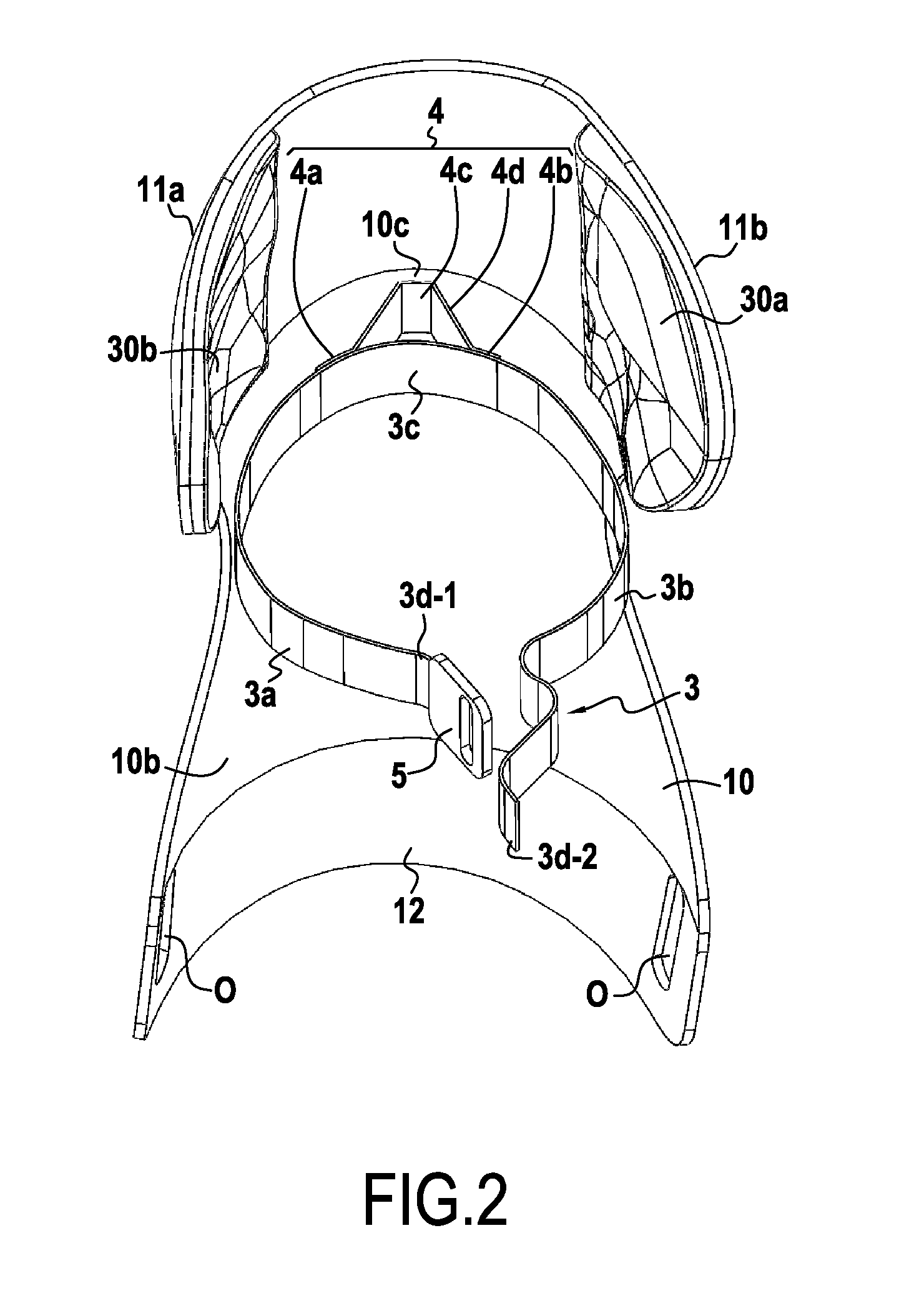
The present invention relates to a device for protecting a user's knee joint, the device being for installing on a sports boot (2) and being characterized in that it comprises a shell (10) provided with an inside surface suitable for covering at least in part an anterior portion of the user's leg, the shell (10) having a top portion (11) for situating at knee level and a bottom portion (12) including connection means suitable for connecting the shell (10) to the sports boot (2), the top portion including side cheeks suitable for being put into contact with the knee on either side of the knee, and coming into contact at least with the condyles of the user's femur, at least one strap (3) for attaching around a zone of the leg and attachment means for attaching the strap (3) to the inside surface of the shell (10).

Description

FIELD OF THE INVENTION[0001]The invention relates to a device for protecting a user's knee joint, which device is for installing on a sports boot. The invention relates to a device for protecting a user's knee joint, which device comprises a shell surrounding part of the anterior and side portions of the tibia and of the knee, the shell being fitted with a strap suitable for controlling rearward movement in translation of the knee relative to the shell. The invention also relates to equipment incorporating such a device, and to a sports boot.[0002]The invention thus finds a particular application in practicing sports or leisure pursuits in which the knee joint is highly stressed, including board sports (including downhill skiing, monoskiing, snow boarding, cross-country skiing) and roller sports (including roller blades and roller skates).BACKGROUND OF THE INVENTION[0003]The practice of the above-mentioned activities leads every year to numerous conditions associated with the knee j...

Claims


Application Information

Patent Timeline
Patent Type & Authority Applications(United States)
IPC IPC(8): A41D13/00
CPCA41D13/0015A63B71/1225A63B2071/125A63B2071/1258A43B5/0415A61F5/0106A41D13/065
Inventor GOUNIOT, PIERRE
Owner GOUNIOT PIERRE
Learn More