
Device and methods for installing elevator cab interior wall panels

Active Publication Date: 2015-02-12
G & R ELEVATOR MFG
View PDF15 Cites 0 Cited by
  • Summary
  • Abstract
  • Description
  • Claims
  • Application Information

AI Technical Summary

Benefits of technology

The present invention provides devices and methods for accurately installing elevator wall panels and reveal strips in a timely manner. This is achieved by using corner stays and intermediate stays with pre- installed clips and locating means to facilitate accurate locating of adjacent stay(s). Also, pre-installing the reveal strips further reduces the labor and time required at the installation site. The technical effect is improved efficiency and accuracy in elevator panel installation.

Problems solved by technology

As a result, each individual mating clip requires a significant amount of measurement effort to obtain the proper installation location.
This is a time consuming, laborious process.
This process is laborious, tedious and time consuming and, as a result, costly.

Method used


Image

  • Device and methods for installing elevator cab interior wall panels
  • Device and methods for installing elevator cab interior wall panels
  • Device and methods for installing elevator cab interior wall panels

Examples


embodiment 200

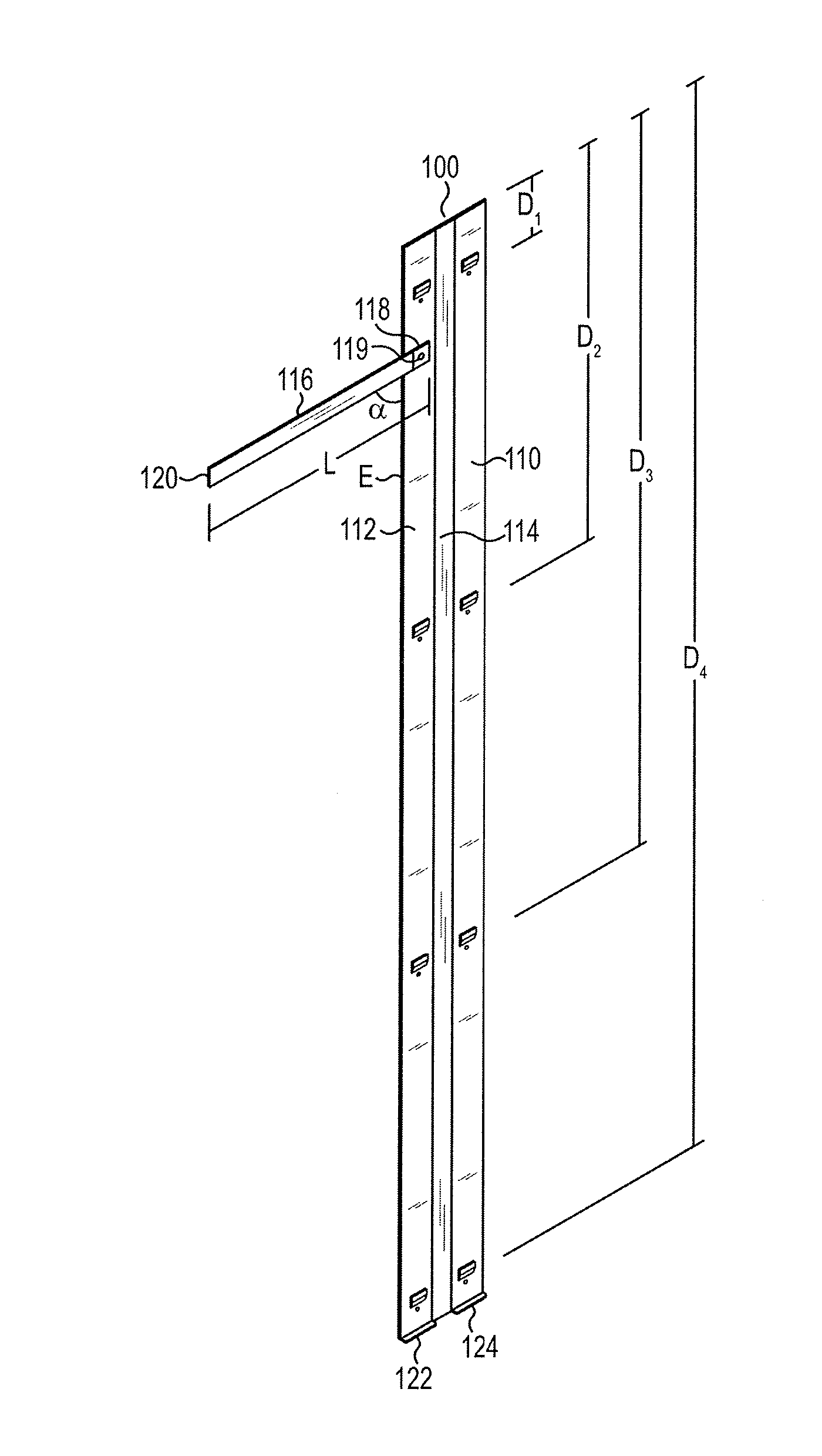
[0039]FIGS. 8-9 illustrate another stay embodiment 200 which is essentially a mirror image of stay 100 described above. Thus, stay 200 may comprise a front side 202, a rear side 204, a top 206, a bottom 208, a right side 210, a left side 212, and a center portion 214 that is vertically integrated and disposed between the right side 210 and the left side 212. Stay 200 may comprise right side 210, left side 212 and center portion 214 being substantially parallel with each other.

[0040]In addition, a plurality of through holes 213, disposed on the right side 210, and left side 212, of the stay 200 are provided, as illustrated in pairs but may be in any configuration as understood by the skilled artisan. One half of through holes 213 pairs may be disposed on the right side 210 of stay 200 and the other half of the through holes 213 may be disposed on the left side 212 of the stay 200. Through holes 213 are provided for securing the stay to the wall W of the elevator cab shell 10 with a f...

embodiment 300

[0045]FIGS. 10-12 illustrate another stay embodiment 300. Thus, stay 300 may comprise a front side 302, a rear side 304, a top 306, a bottom 308, a right side 310, a left side 312, and a center portion 314 that is vertically integrated and disposed between the right side 310 and the left side 312.

[0046]Stay 300 comprises a corner piece for fitting on adjacent elevator cab shell walls W and may comprise right side 310, left side 312 and center portion 314 wherein center portion comprises an angle β. Angle β preferably comprises 90 degrees, though other angles are within the scope of the invention as the skilled artisan will readily recognize. Note that 90 degrees in this context accommodates elevator shell walls W that are disposed at right angles to each other. In the case of non-right angled elevator walls W, angle β may be modified to complement the actual angle formed by the adjacent elevator walls W. Each angle β is within the scope of the present invention.

[0047]As a consequenc...


PUM


Abstract

The present invention is directed to, inter alia, devices and methods for precision installation of elevator wall panels and intervening reveal strips in an elevator cab shell. Various embodiments comprise corner stays and intermediate stays with pre-installed clips thereon and with locating means installed thereon to facilitate accurate locating of adjacent stay(s) in order to greatly reduce the labor and time required to install the wall panels accurately. Further, various embodiments comprise pre-installed reveal strips on the stay(s) and that are interposed between each installed wall panel. Pre-installing the reveal strips further reduces the labor and time required at the installation site.

Description

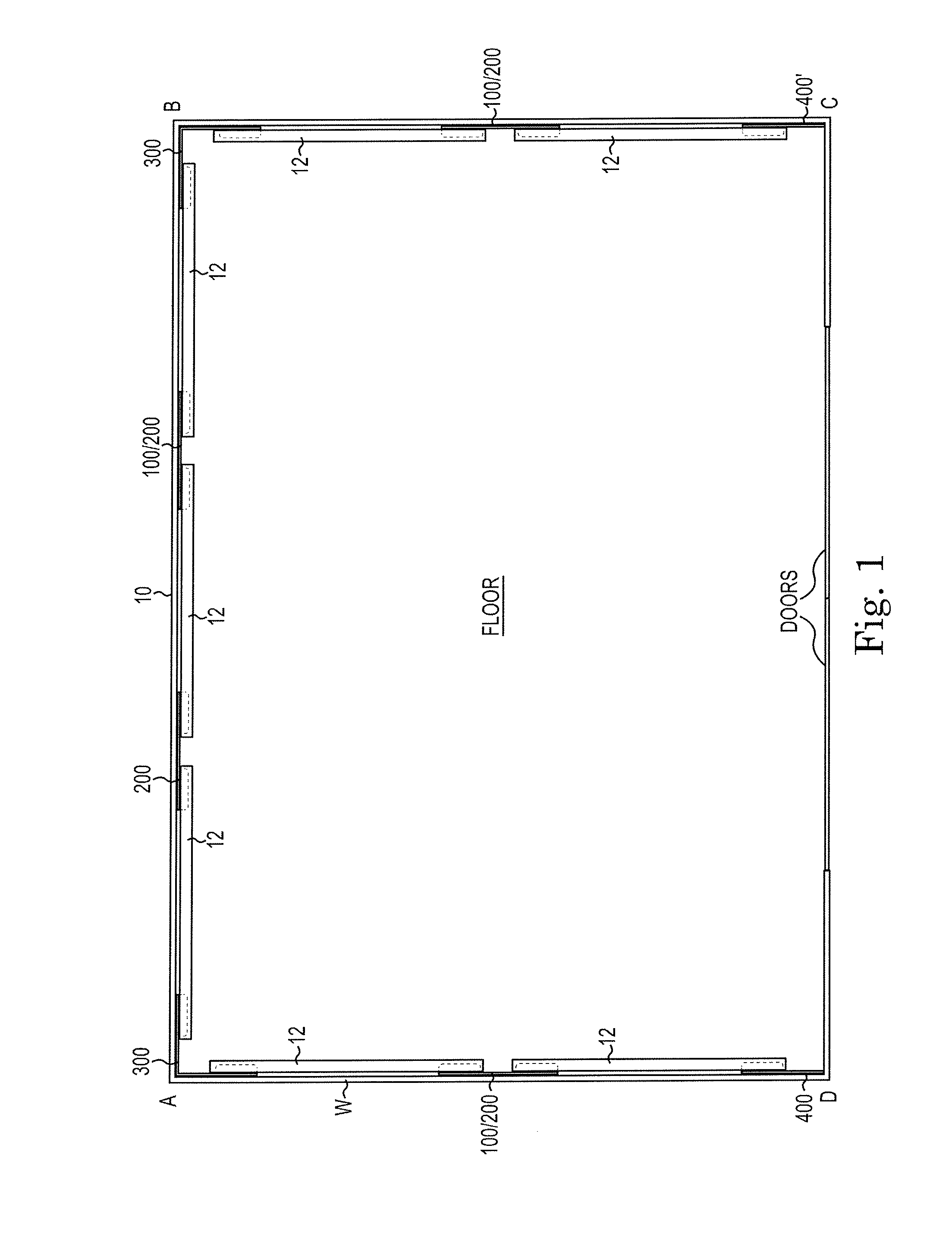
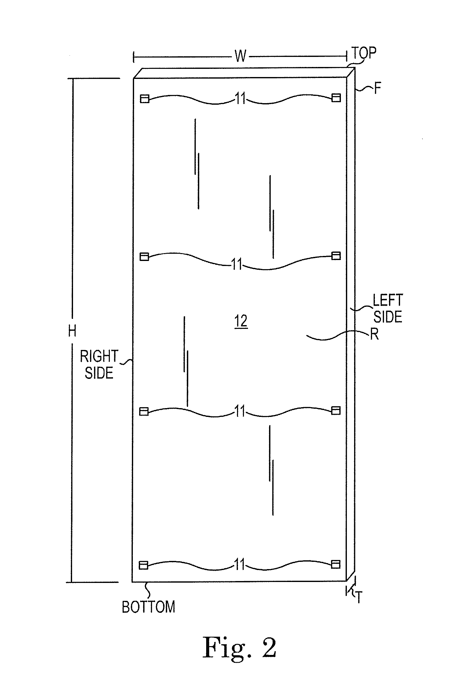
CROSS-REFERENCE TO RELATED APPLICATIONS[0001]NoneBACKGROUND OF THE INVENTION[0002]1. Field of the Invention[0003]The present invention is directed to devices and methods for installing elevator cab interior wall panels. More particularly, an installation template for locating and installing elevator cab interior wall panels is provided.[0004]2. Description of the Related Art[0005]The interior of finished elevator cab shells typically comprise wall panels installed and mounted thereon. Typically, to complete the installation of the wall panels on the elevator cab shell, zee-type clips are pre-installed on rear side of the wall panels. These pre-installed zee clips require, in turn, mating clips to be field installed onto the elevator cab shell. These mating clips require accurately measured locating on the elevator cab shell in order to precisely mate up with the pre-installed zee clip on rear of the wall panel for hanging and securing installation.[0006]There are typically a plurali...

Claims


Application Information

Patent Timeline
IPC IPC(8): B66B11/02
CPCB66B11/0253
Inventor PERSONS, JR., KENMAVEUS, DARRENHUDAK, STEVE
Owner G & R ELEVATOR MFG
Learn More