Liquid ejecting head and liquid ejecting apparatus

a liquid ejecting and liquid technology, applied in the direction of printing, movable spraying apparatus, inking apparatus, etc., can solve the problem of decreasing the rigidity of the structure forming the pressure chamber, and achieve the effect of increasing the rigidity of the partition wall, increasing the rigidity of the portion overlap, and improving the structural strength of the pressure chamber

Active Publication Date: 2015-01-29
SEIKO EPSON CORP
View PDF1 Cites 11 Cited by
  • Summary
  • Abstract
  • Description
  • Claims
  • Application Information

AI Technical Summary

Benefits of technology

The technical effect of this patent is to improve the strength of a pressure chamber.

Problems solved by technology

However, it is considered that as the density of the nozzles increases, the partition wall separating the pressure chambers from each other becomes thinner and the thus the rigidity of a structure forming the pressure chamber decreases.
Moreover, such a problem is not limited to the ink jet head and also similarly exists in various liquid ejecting heads and liquid ejecting apparatuses.

Method used


Image

  • Liquid ejecting head and liquid ejecting apparatus
  • Liquid ejecting head and liquid ejecting apparatus
  • Liquid ejecting head and liquid ejecting apparatus

Examples


modification example

4. Modification Example

[0074]In the invention, various modifications can be considered.

[0075]For example, the liquid ejected from the liquid ejecting head includes a fluid and the like such as a solution in which dyes and the like are dissolved in a solvent and a sol in which solid particles such as pigments or metal particles are dispersed in a dispersion medium. Such a fluid includes ink, liquid crystal, and the like. The liquid ejecting head may be mounted on an apparatus for manufacturing a color filter for a liquid crystal display and the like, an apparatus for manufacturing the electrodes of an organic EL display and the like, an apparatus for manufacturing biochips, and the like in addition to an image recording apparatus such as the printer.

[0076]The common liquid chamber that supplies the liquid to the pressure chamber may be provided only in the flow path substrate without being provided in a separate member such as the case head, and may be provided only in the separate m...


PUM


Abstract

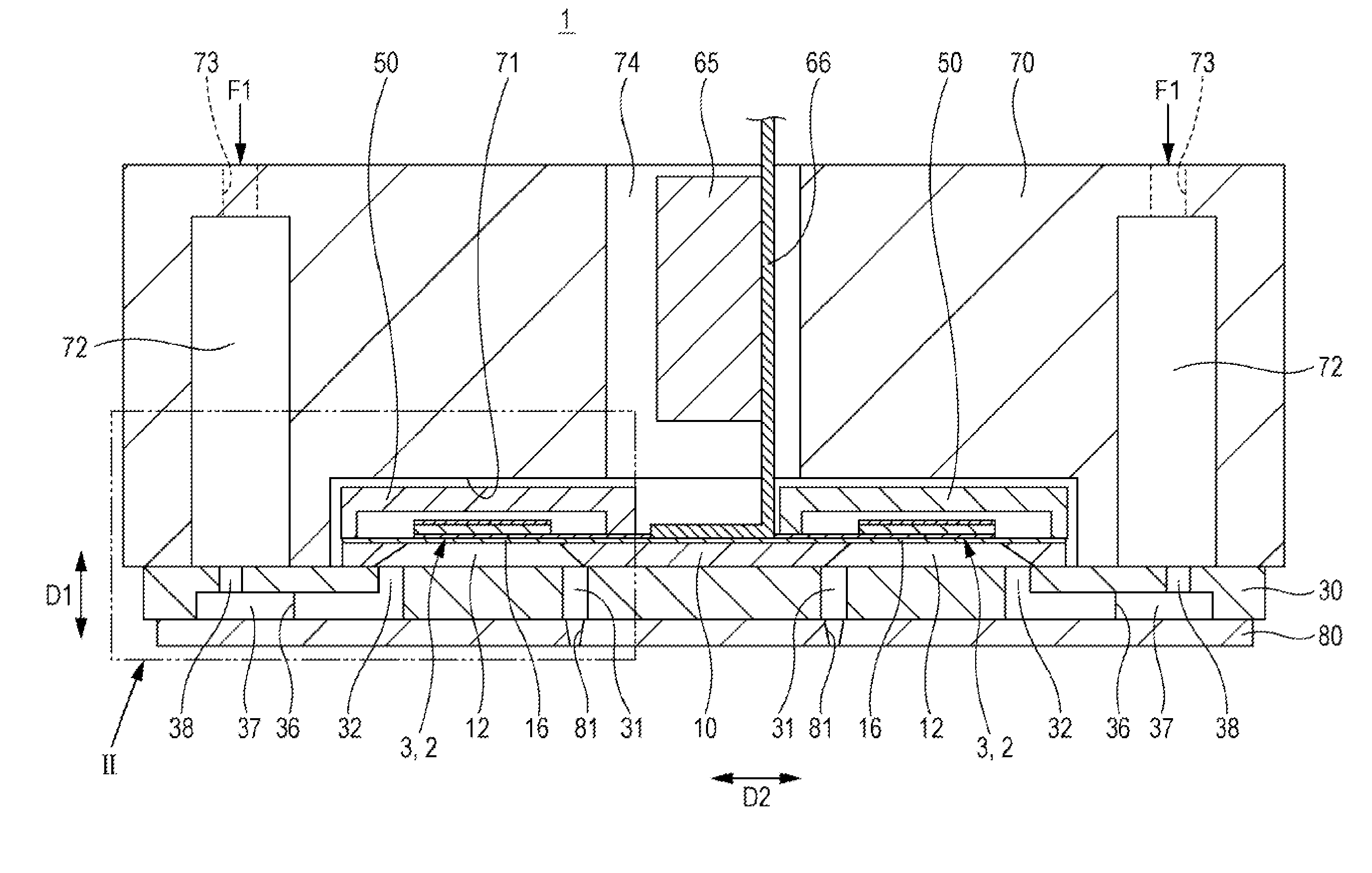
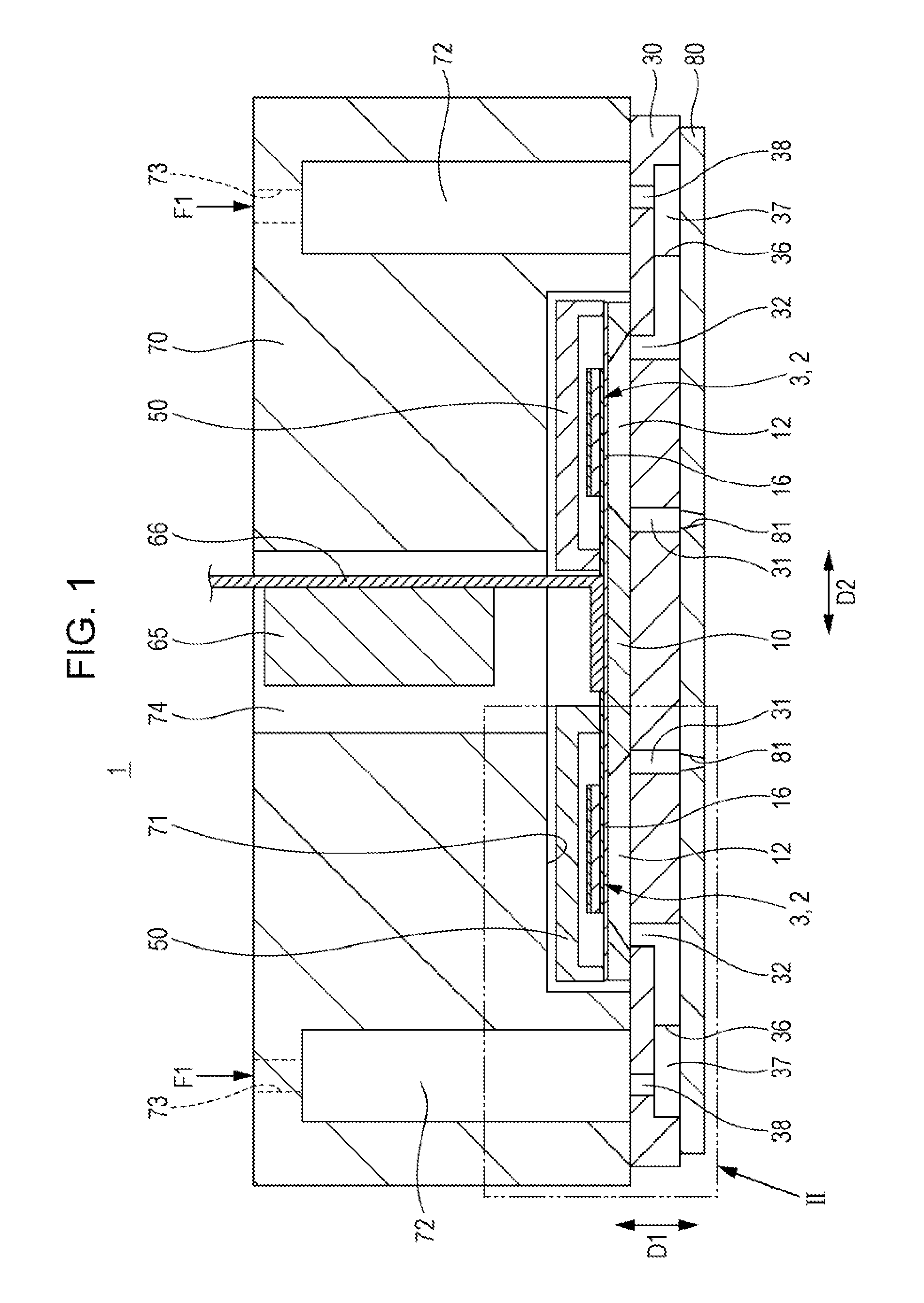
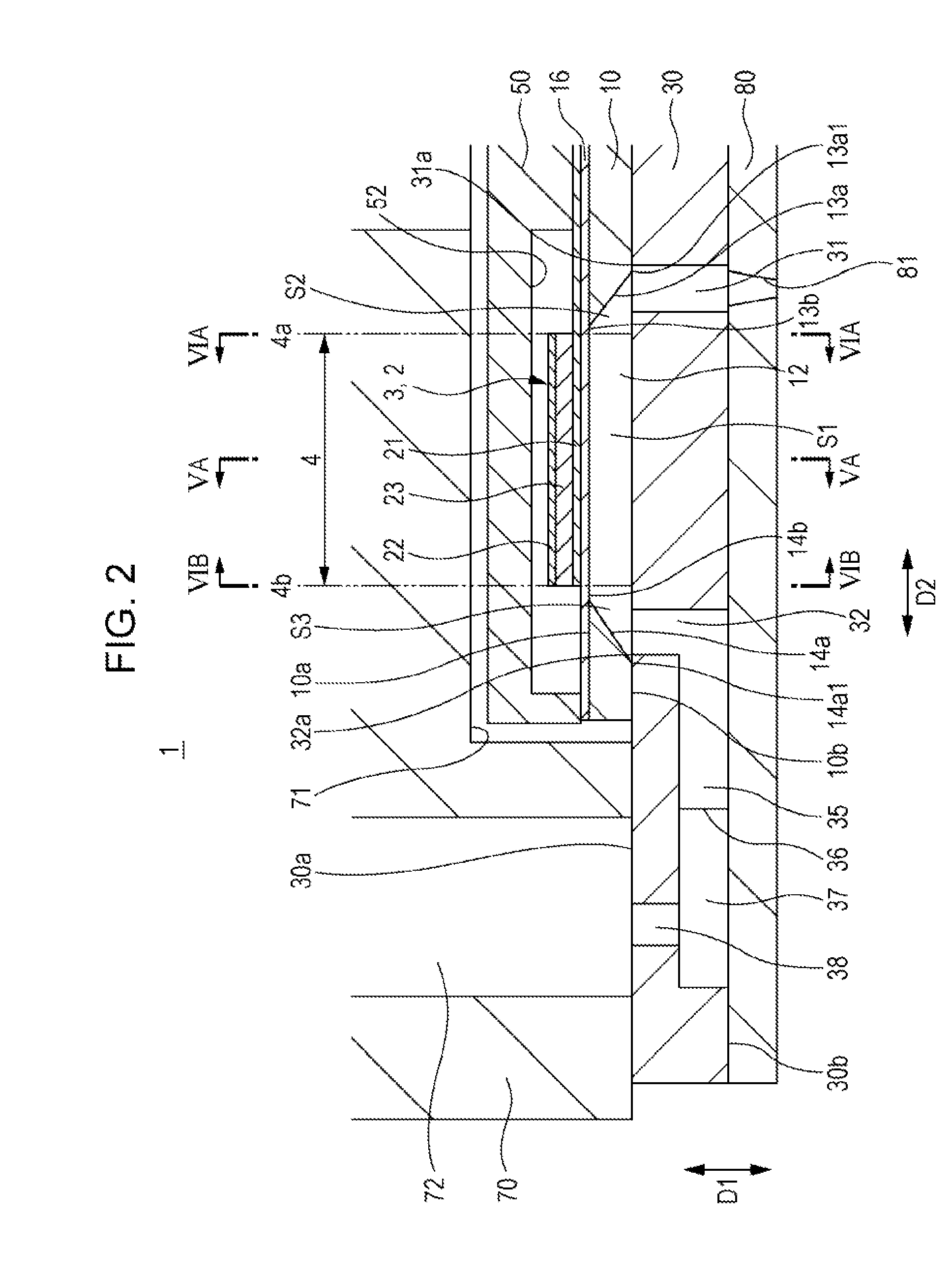
A liquid ejecting head in which a flow path substrate having a communication hole communicating with a nozzle and a pressure chamber substrate having a space that is a pressure chamber are at least laminated includes: an actuator having an active section that is interposed between electrodes and applies pressure to the pressure chamber. The pressure chamber substrate has a first space positioned in a region corresponding to the active section and a second space positioned nearer to the nozzle than the first space and communicating with the first space among the spaces. The communication hole does not overlap with the first space and overlaps with at least a part of the second space in a lamination direction.

Description

BACKGROUND[0001]1. Technical Field[0002]The present invention relates to a liquid ejecting head and a liquid ejecting apparatus.[0003]2. Related Art[0004]A known liquid ejecting head (for example, JP-A-2011-213123) includes an ink jet head that includes a flow path unit in which pressure chambers separated by partition walls are respectively arranged in a longitudinal direction) as well as a piezoelectric actuator for applying pressure to ink inside each pressure chamber. In the flow path unit, a pressure chamber plate, a base plate, a manifold plate, and a nozzle plate are laminated to each other. A through hole communicating with the nozzle is formed directly below the pressure chamber in the base plate and the manifold plate. Furthermore, a through hole communicating with the manifold is formed directly below the pressure chamber in the base plate.[0005]In recent years, a high quality of output (such as a printed matter) is required resulting in increasing nozzle density. However...

Claims


Application Information

Patent Timeline
Patent Type & Authority Applications(United States)
IPC IPC(8): B05B17/06
CPCB05B17/0676B41J2/14233B41J2002/14241B41J2002/14491B41J2202/11B41J2/14201B41J2/14274
Inventor FUKUDA, SHUNYA
Owner SEIKO EPSON CORP
Why Eureka
Try Eureka