
Electronic device and method for controlling image display

a technology of electronic devices and image displays, applied in the field of electronic devices, can solve the problems of blurred or out of focus images, unstable hands of users, and unstable electronic devices, and achieve the effect of limited viewing angles for photographic composition

Active Publication Date: 2015-01-15
SAMSUNG ELECTRONICS CO LTD
View PDF11 Cites 36 Cited by
  • Summary
  • Abstract
  • Description
  • Claims
  • Application Information

AI Technical Summary

Benefits of technology

The present invention provides an electronic device with multiple cameras having different viewing angles, which can detect movement and capture images or videos of an object. The device can display the images or videos on a screen simultaneously, and can also alter the photographic capture of the first image based on the movement of the object in the second image. The technical effects of the invention include improved photographic composition and more flexibility in capturing images or videos.

Problems solved by technology

However, often times the user's hand is unstable during the capture process.
As a result, the electronic device is unstable, and resulting images are captured blurred or out of focus.
Additionally, because of the limited viewing angle of the camera mounted to the device, it is impossible to capture images at certain angles.
Manual adjustment is impossible to the extent that the user cannot accurate compose the photograph if the desired angle places the camera out of the user's field of vision.
As described above, as conventional electronic devices now one camera formed on a front surface or on a rear surface thereof, and generally are not configured to detect a movement of a subject or an object, the range of possible viewing angles for photographic composition is limited.

Method used


Image

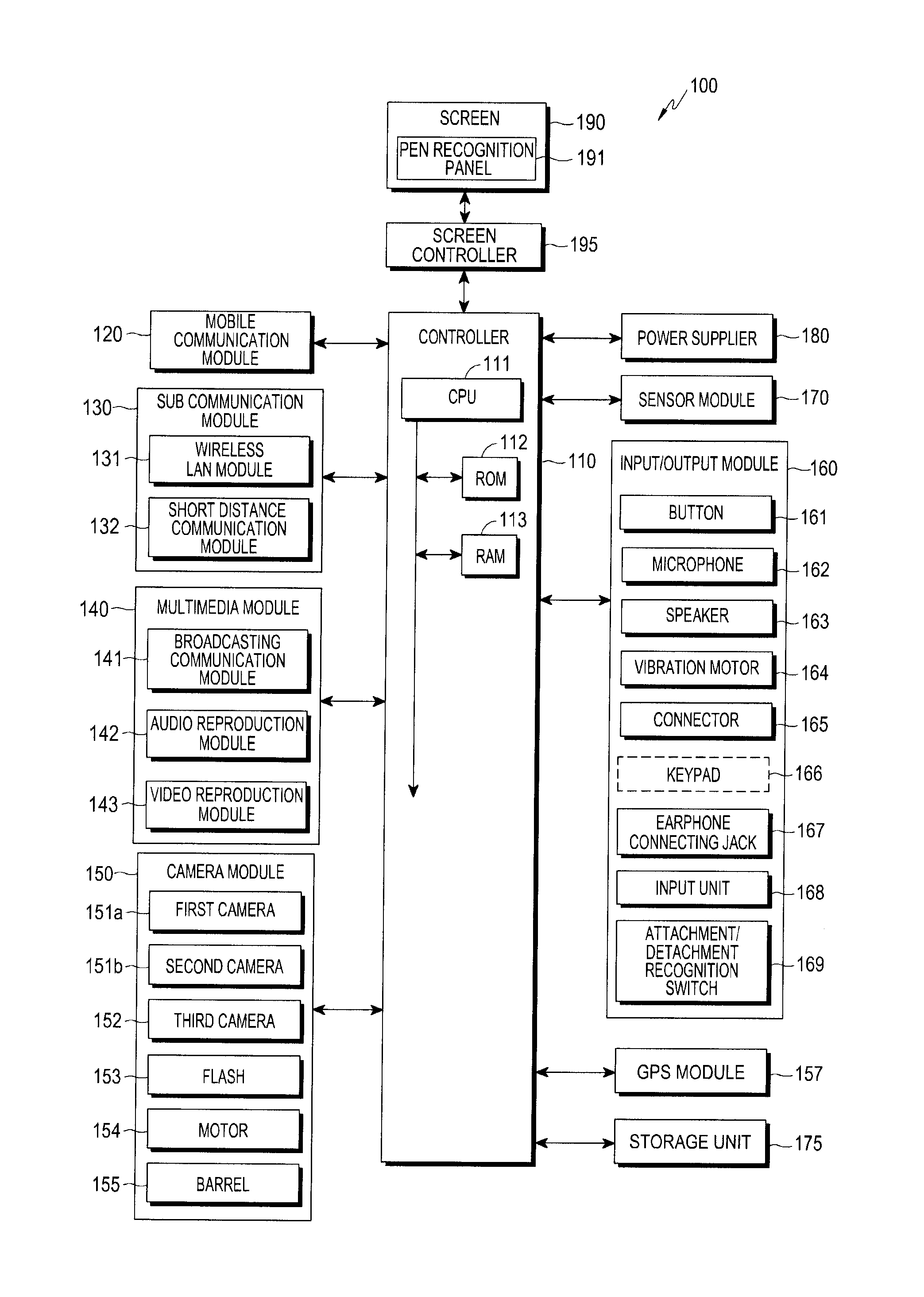
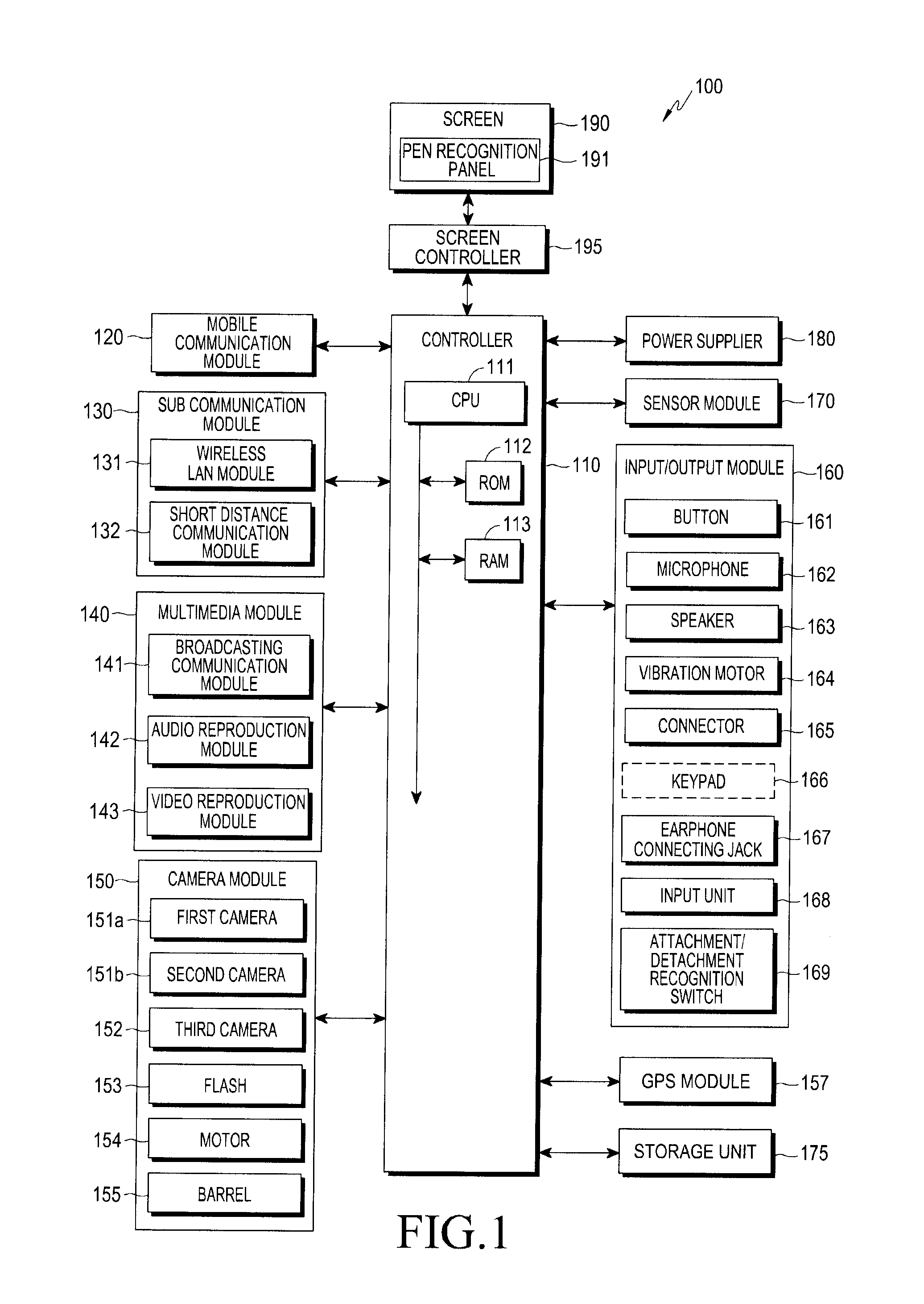
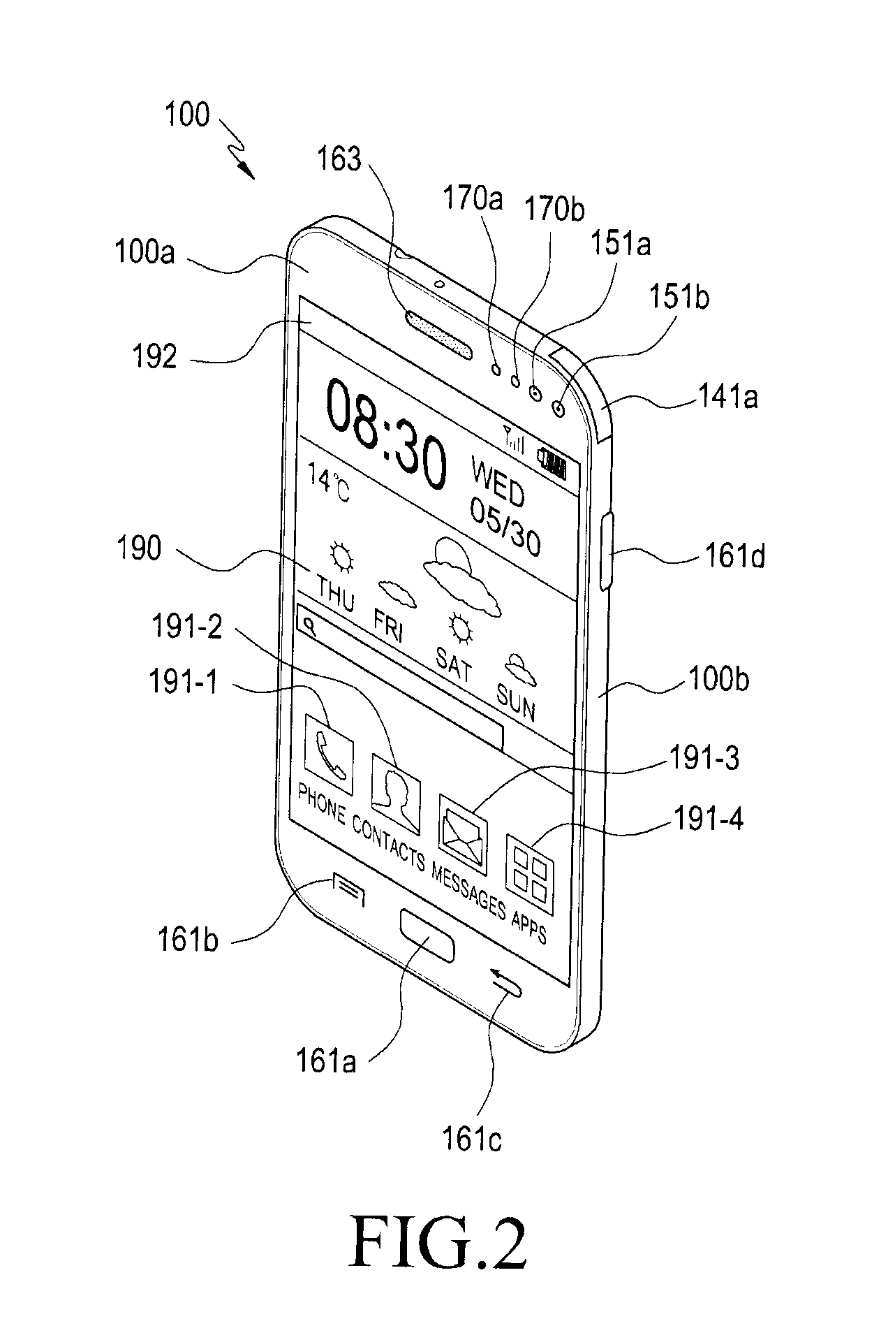
  • Electronic device and method for controlling image display
  • Electronic device and method for controlling image display
  • Electronic device and method for controlling image display

Examples


Embodiment Construction

[0042]Various example embodiments will now be described more fully with reference to the accompanying drawings in which some example embodiments are shown. Therefore, it should be understood that there is no intent to limit example embodiments to the particular forms disclosed, but on the contrary, example embodiments are to cover all modifications, equivalents, and alternatives falling within the scope of the invention.

[0043]While terms including ordinal numbers, such as “first” and “second,” etc., may be used to describe various components, such components are not limited by the above terms. The terms are used merely for the purpose to distinguish an element from the other elements. For example, a first element could be termed a second element, and similarly, a second element could be also termed a first element without departing from the scope of the present invention. As used herein, the term “and / or” includes any and all combinations of one or more of the associated listed item...


PUM


Abstract

An electronic device and a method for controlling photographic capture. A first image is acquired by a first camera having a first viewing angle. A second image is acquired by a second camera having a second viewing angle, the second viewing angle being different from the first viewing angle. The first image is overlaid with at least one object from the second image, or an icon corresponding to the object. The first camera and the second camera are mounted to a same surface, or to disparate surfaces relative to one another. Photographic capture or control is triggered in response to movement of the object.

Description

CLAIM OF PRIORITY[0001]This application claims the priority under 35 U.S.C. §119(a) to Korean Application Serial No. 10-2013-0082287, which was filed in the Korean Intellectual Property Office on Jul. 12, 2013 the entire content of which is hereby incorporated by reference.BACKGROUND[0002]1. Technical Field[0003]The present disclosure relates to an electronic device, and more particularly to, an electronic device and a method for controlling an image display.[0004]2. Description of the Related Art[0005]The services and functions provided by electronic devices such as smart phones, tablets, and laptop computers are continually expanding. In order to increase the utility of electronic devices and to meet the demands of users, various application programs have been developed. Thousands of these applications are available, and can be downloaded, stored and executed on the electronic device, which is highly portable. Electronic devices also have ever increasing multimedia functionality, ...

Claims


Application Information

Patent Timeline
Patent Type & Authority Applications(United States)
IPC IPC(8): H04N5/265H04N5/232H04N23/90
CPCH04N5/23293H04N5/265H04N5/2621H04N23/611H04N23/631H04N23/90H04N23/63H04N23/62G06F3/04817G06F3/0488H04N5/2628H04N5/272
Inventor KIM, MOON-SOOJEONG, JIN-HONGKANG, HWA-YONGYOON, YOUNG-KWONKIM, TAE-HO
Owner SAMSUNG ELECTRONICS CO LTD
Learn More