Marine power generating system and marine power generating method

a power generation system and power generation method technology, applied in the direction of electric generator control, positive displacement liquid engine, machines/engines, etc., can solve the problems of insufficient pressure, slow speed, and no disclosure of the improvement of propeller and turbine, and achieve the effect of suitable water pressur

Inactive Publication Date: 2015-01-15
NISHIOKA TOSHIHISA
View PDF6 Cites 7 Cited by
  • Summary
  • Abstract
  • Description
  • Claims
  • Application Information

AI Technical Summary

Benefits of technology

[0049]According to the present invention of the marine power generation system, the seawater drop pipe is set vertically in the ocean, so it can supply the space with in vertical difference between ocean surface and the submersible body similar to a water discharge from a dam, which is suitable for hydroelectricity power generation.
[0050]The forced discharge of the seawater dropped in the submersible body to the outer undersea is conducted by the piston-cylinder style discharge mechanism with the first check valve and the second check valve for preventing a countercurrent. It may call a “natural power discharge” utilizing the power of the tidal current flowing around the submersible body. If the forced discharge of the seawater is conducted by the pump style discharge mechanism, it may call as a “forced power discharge” using electricity obtained from the power of the tidal current flowing around the submersible body.
[0051]The piston-cylinder style discharge mechanism discharges the seawater from the seawater tank space of the submersible body with low water pressure to the outer undersea of the submersible body with high water pressure. However, the piston motion can be achieved if there is strong water pressure in the tidal current. The velocity of the tidal current is not important. The seawater amount to be dropped through the seawater drop pipe depends on the volume of the vacant space in the seawater tank space of the submersible body obtained by the piston-cylinder style discharge mechanism. The seawater dropping through the seawater drop pipe can be dropped at a suitable velocity and suitable water pressure for the hydroelectric power generation
[0052]The same as the piston-cylinder style discharge mechanism, the pump style discharge mechanism also discharges the seawater from the seawater tank space of the submersible body with low water pressure to the outer undersea of the submersible body with high water pressure. The electricity for driving the pump style discharge mechanism is obtained by the generator installed around the submersible body, and the seawater in the seawater tank space of the submersible body is discharged forcibly. The seawater amount to be dropped through the seawater drop pipe depends on the volume of the vacant space in the seawater tank space of the submersible body obtained by the pump style discharge mechanism. The seawater dropping through the seawater drop pipe can be dropped at a suitable velocity and the suitable water pressure for the hydroelectric power generation.
[0053]As shown above, according to the present invention of the marine power generation system, the tidal current which is relatively low velocity can be converted to the suitable velocity and the suitable water pressure for hydroelectric power generation.

Problems solved by technology

However, the speed is slow and the pressure is not enough for rotating the propeller and the turbine of the power generator.
However, there is no disclosure about improvement of the propeller and the turbine.
The technology disclosed in prior 1 is not enough for obtaining the electromotive force by rotating the large scale power generator efficiently.
However, the rotating speed of the first propeller and the second propeller is very low, so the rotary gear ratio becomes too large to drive the large scale power generator at the normal rotation speed.
The required torque for rotating the large scale power generator at the normal speed is generated by the torque obtained from the tidal current via the rotary gear, so the rotary gear faces a large mechanical load.
The mechanical load may exceed the mechanical strength to break.

Method used


Image

  • Marine power generating system and marine power generating method
  • Marine power generating system and marine power generating method
  • Marine power generating system and marine power generating method

Examples


embodiment 1

[0069]The marine power generation system 100 in embodiment 1 according to the present invention is described.

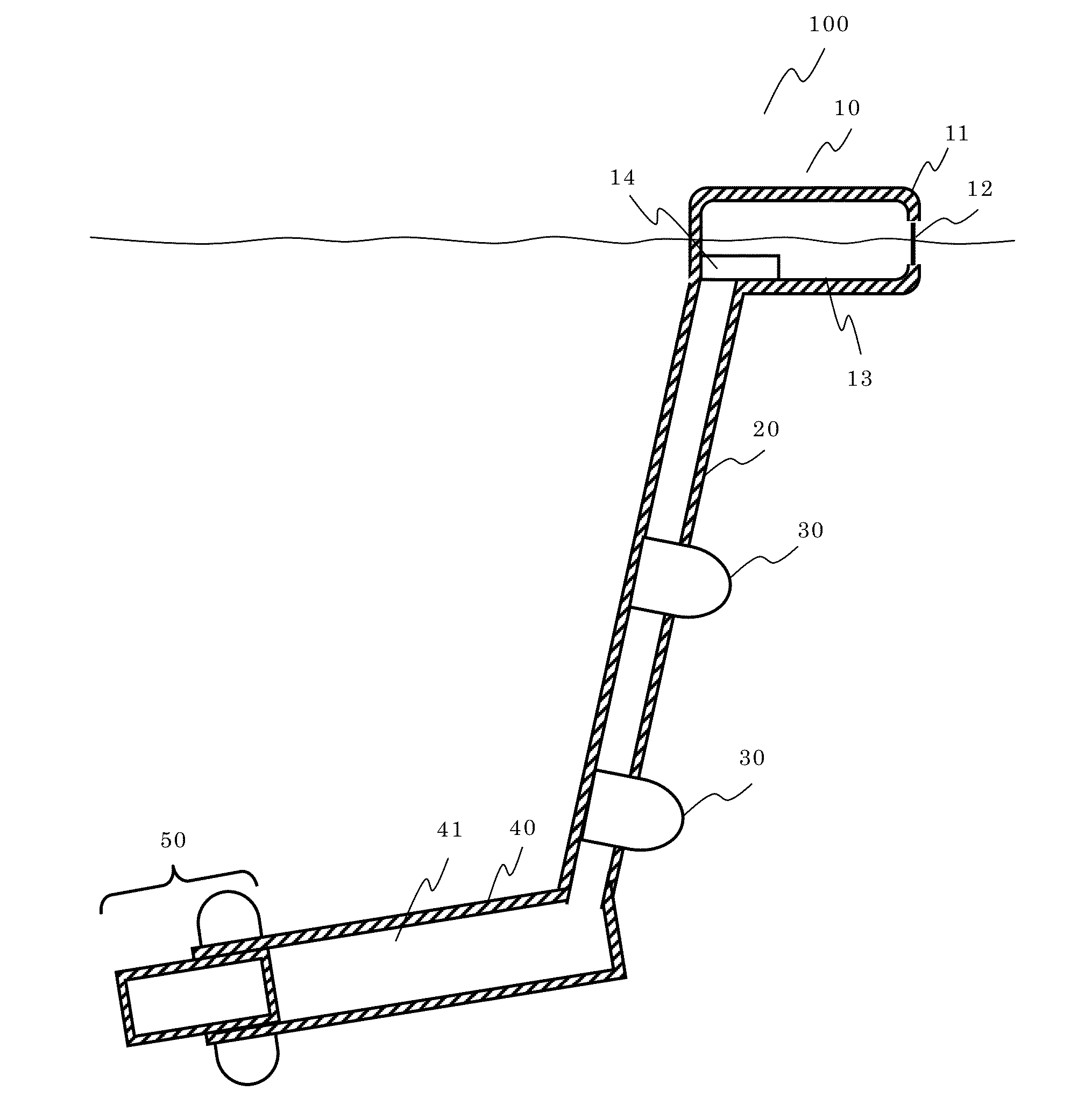
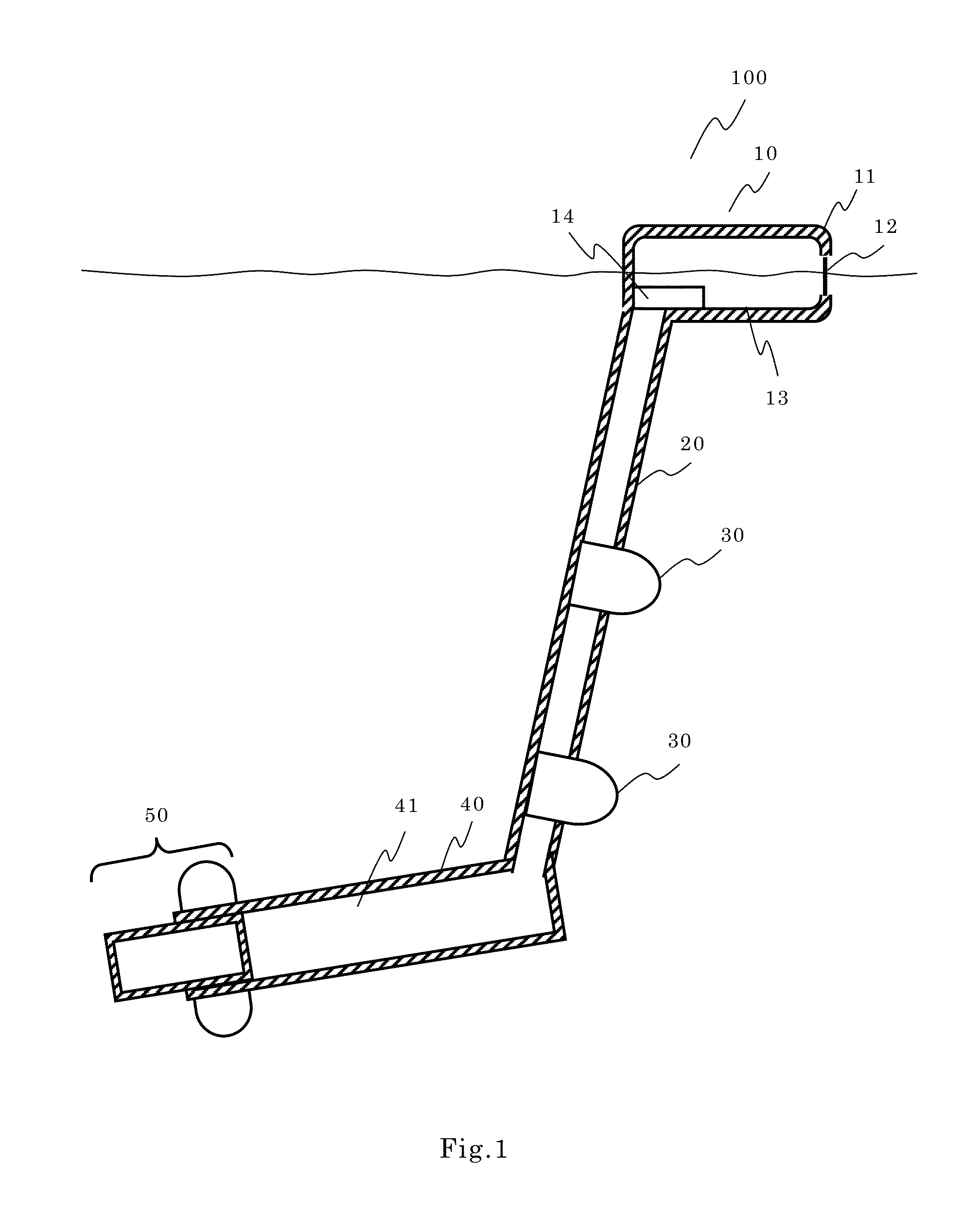
[0070]FIG. 1 is a schematic view of the configuration of the marine power generation system 100 according to the present invention.

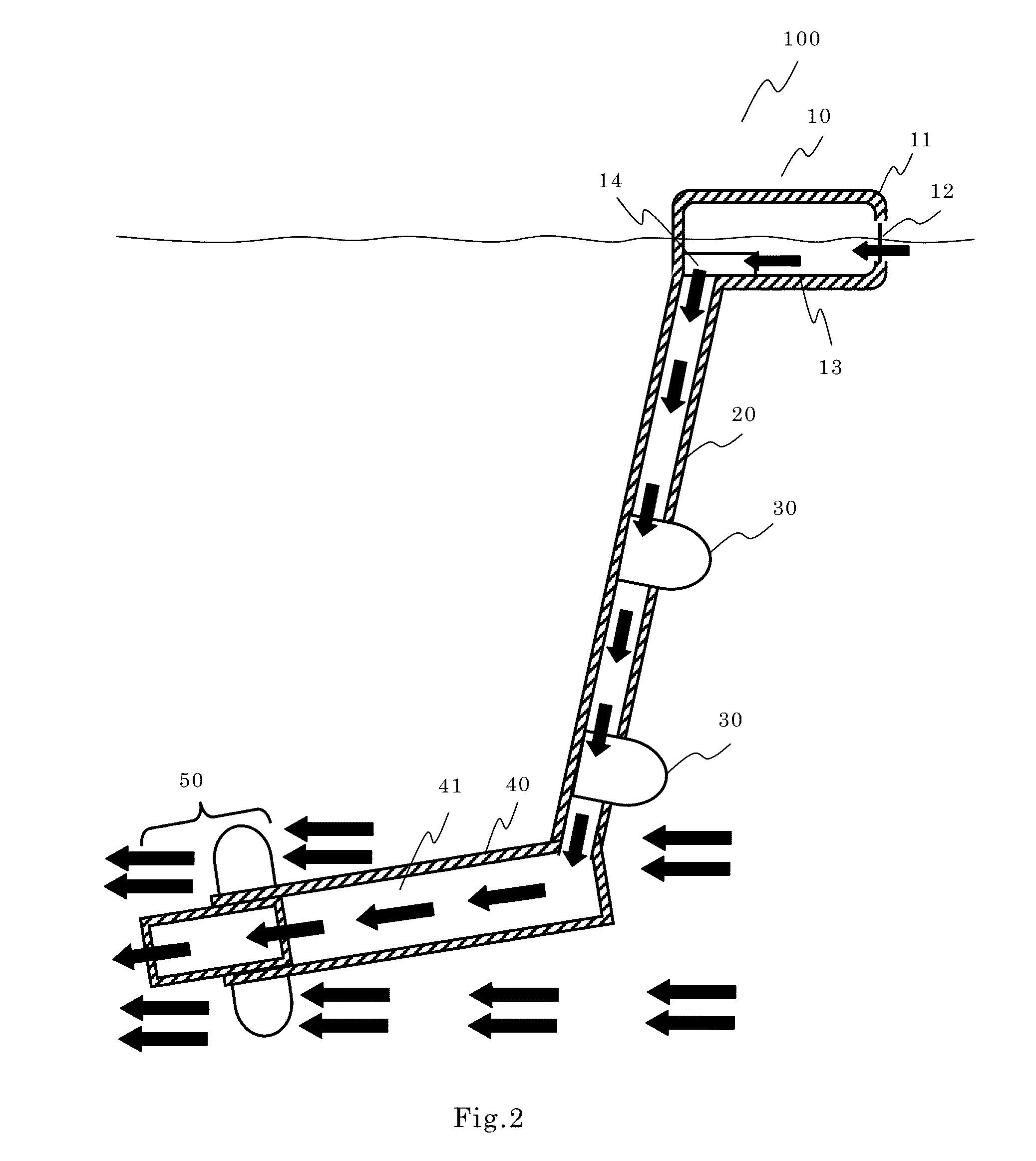
[0071]FIG. 2 is a schematic view showing the seawater flow.

[0072]As shown in FIG. 1, the marine power generation system 100 comprises a seawater intake structure 10, a seawater drop pipe 20, a generator 30, a submersible body 40 and a forced discharge part 50. As shown in FIG. 2, there are seawater flows inside and outside of the marine power generation system 100. The marine power generation system 100 generates power by the taken-in seawater flow drop in the system and the tidal current flow around the system.

[0073]Hereinafter, each component is explained, then the operation of the marine power generation system 100 is explained.

[0074]Each component is explained as follows.

[0075]The seawater intake structure 10 may be a structure constructed on ...

embodiment 2

[0154]The second marine power generation system 100a in embodiment 2 according to the present invention is described. In the second marine power generation system 100a shown in this embodiment 2, the pump mechanism is employed in the forced discharge part.

[0155]The marine power generation system 100a shown in this embodiment 2 discharges the seawater in the forced discharge part 50a by the pump mechanism 58.

[0156]Other components such as the seawater intake structure 10, the seawater drop pipe 20, the power generators 30, the submersible body 40, and the other components, which are not explained specifically in Embodiment 2, may be the same as that of Embodiment 1. Regarding these other components, descriptions and drawings are omitted here.

[0157]FIG. 10 is a schematic view showing the forced discharge part 50a employing the pump style discharge mechanism of the Embodiment 2. FIG. 10 shows the discharge operation simply, so fine details of the mechanical components and configuration...


PUM


Abstract

[Problem] To provide a marine power generation system which is engineered to be able carry out power generation stably and highly efficiently, using the large source of energy even in ocean currents having insufficient speeds to create a water current, similar to a water discharge from a dam, which is ideal for hydroelectricity.
[Solution] As an example of a water intake structure (10), a sea surface floatation object, floats on the sea by buoyancy, and has an aperture part (12) through which seawater is taken therein. A water guide pipe (20) is underwater, which secures a space underwater. One end of the water guide pipe (20) is connected to the sea surface floatation object (10), and the seawater which is taken in from the sea surface floatation object which is the water intake structure (10), is introduced downward under the sea surface. Power generators (30) that generate power from either the falling motion of the seawater or water pressure are in the water guide pipe (20), and carry out power generation. A submersible body (40) is in the water, and an accumulation space (41) is provided that takes in the seawater which is discharged from another end of the water guide pipe (20). The seawater that is taken into the accumulation space (41) in the submersible body (40) is discharged outward from the submersible body (40) by a discharge part (50).

Description

TECHNICAL FIELD[0001]This invention relates to a marine power generation system and a marine power generating method.BACKGROUND ART[0002]With the rapid increase of the energy demands on the global scale, various research and development are actively promoted for utilizing a natural energy source without the fear of scarcity and pollution from the new energy source or the alternative energy source instead of the traditional fossil fuels such as oil and liquefied natural gas (LNG), and nuclear energy on which we now depend.[0003]As the power generation method for utilizing the natural energy source, the wind power generation for utilizing the wind power and the marine power generating for utilizing the tidal current source are researched and developed. Regarding the wind power generation, the generated power amount is unstable because of the fluctuation of the wind amount. However, with the marine power generation, the generated power amount is stable because the tidal current is rela...

Claims


Application Information

Patent Timeline
Patent Type & Authority Applications(United States)
IPC IPC(8): F03B13/10
CPCF03B13/10F03B13/00F03B17/06F04B17/06F04B23/02F05B2240/97Y02E10/20Y02E10/30
Inventor NISHIOKA, TOSHIHISA
Owner NISHIOKA TOSHIHISA
Why Eureka
Try Eureka